Product Overview
The Accutherm explosion-proof immersion heater is built and certified to heat fluids inside a classified (hazardous) location — an area with flammable gas, vapor, or combustible dust where an ordinary heater would be an ignition source. The flagship Series 72 flange build carries North American (CSA / NEC), ATEX, and IECEx markings — Class I, Divisions 1 & 2, Groups B/C/D and Class II, Division 1, Groups E/F/G, with an IP66 explosion-proof enclosure — and a pipe-thread EP build covers smaller, horizontal CSA Class I Div 1 installs. The element, sheath, and watt-density platform is the same proven Aspeq immersion design; the difference is the certified hazardous-area enclosure, construction, and data-plate marking. Use the input form to send the area classification, the Group, and the required T-code — a hazardous-area rating is never approximated.
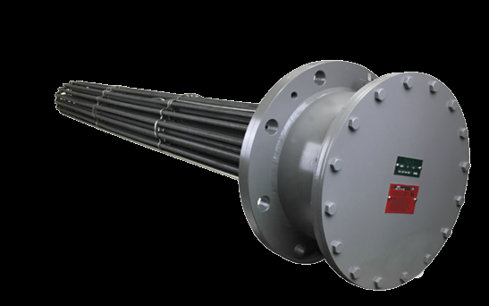
Key Features & Benefits
- Certified to go where a standard heater cannot — this is an immersion heater built and marked for a classified (hazardous) area — flammable gas or vapor, or combustible dust — where an ordinary heater is an ignition source. The right answer when the area classification, not the heat load, is what rules the spec.
- North American and international markings on one line — the Series 72 flange build carries CSA / NEC, ATEX, and IECEx markings, so the same heater suits a domestic plant or an export / offshore project without re-engineering. One certified product for stateside and export work.
- Flange or pipe-thread, matched to the vessel — the flagship Series 72 flange build mounts vertical or horizontal to a mating flange; the pipe-thread EP build threads into an NPT fitting for smaller, horizontal installs. The hazardous-area rating, in the mounting your vessel already takes.
- Sheath temperature held under the T-code by design — the elements are spaced for even heat and free expansion so no hot spot pushes the sheath past the certified temperature code — the construction detail that keeps an exposed-element heater compliant. The hazard limit, engineered into the element, not just the paperwork.
- Built to the fluid as well as the atmosphere — the same Aspeq immersion platform underneath means the sheath alloy and watt density are matched to your actual process fluid; corrosive duty can carry a Type 4X enclosure on the pipe-thread build. Hazardous-area rated and fluid-correct, not one at the expense of the other.
Specifications
- Operating principle
- Electric resistance (Joule) heating — AC current passes through a high-resistance nickel-chrome coil in compacted magnesium-oxide insulation inside a metal sheath. On the explosion-proof build the heater is the same immersion element bundle as a standard flanged or pipe-thread heater, but the terminal enclosure, construction, and markings are built and certified so the unit is not an ignition source in a classified (hazardous) atmosphere.
- Mounting / installation
- Two mounting builds under one line. Series 72 flange EP mounts to a mating flange on an enclosure, tank, or pipe line, vertical or horizontal as stamped on the data plate (orientation is part of the certified rating). Pipe-thread EP threads into an ANSI NPT fitting and is horizontal-mount only. The heater must be installed in the marked orientation to maintain the ignition-temperature rating.
- Flange sizes & ratings
- Series 72 mounts by a flange that mates to your mounting flange; the flange size, bolt pattern, and element-bundle length are built to the application and stamped on the data plate. Element bundles 30″ or less need no internal support; longer bundles are supported within 6″ of the U-bend end and on maximum 24″ centers. Allow pull space at least equal to the heater’s overall length plus 3 ft, and 3 ft of work space around the flange and terminal box.
- Pipe-thread sizes
- The pipe-thread EP build uses an integral tapered ANSI NPT mounting fitting with a wrench hex; install only into a mating ANSI NPT fitting. Keep the piping or tank clear of obstructions for the element length plus 3–6″, and allow pull space opposite the fitting equal to the element length. Tank installs with elements over 36″ need element supports on 36″ centers.
- Element construction
- Compacted tubular elements, magnesium-oxide filled, with element spacers that hold the elements apart for free thermal expansion. On a hazardous-area heater the spacing matters twice over: it prevents the localized hot spot that could push the sheath temperature above the certified T-code, which on an exposed element is itself the ignition limit. Do not nick or scratch the flange mating surfaces, and do not lift the heater by the elements.
- Sheath materials
- Sheath material is matched to the process fluid and maximum temperature, drawn from the same Aspeq immersion platform as the standard immersion lines (see the sheath / watt-density table below). Each alloy carries a certified maximum sheath temperature that the build must respect (per CSA C22.2 No. 72): copper 177°C (350°F), Monel 400 482°C (900°F), steel / titanium 399°C (750°F), 300-series stainless 760°C (1400°F), Incoloy 800 927°C (1700°F), and Inconel 600 982°C (1800°F). Heaters labeled accordingly may also suit Type 3, 4, and 4X corrosive environments. The wetted sheath and the hazardous-area rating are specified together — the fluid drives the sheath, the atmosphere drives the enclosure and T-code.
- Process / fluid temperature
- Maximum process / fluid temperature is built to the application and stamped on the data plate. On an EP heater the data-plate maximum is also the limit the process or exposed sheath may reach after the high-temperature limit control operates — it is not the limit-control setpoint. Match the sheath, fluid, and watt density to the maximum process temperature (see the sheath / watt-density table below).
- Watt density
- Watt density (W/in² of element surface) is matched to the fluid and the maximum process temperature (see the table below) — doubly important on a hazardous-area heater, because the sheath temperature has to stay under the certified T-code. The full per-fluid sheath-and-watt-density table is the same Aspeq immersion platform data and travels with the quote.
- Fluid & sheath compatibility
- The Aspeq immersion platform publishes a per-fluid sheath-and-watt-density selection table covering 90+ process fluids — water, glycols, fuel and heat-transfer oils, caustics, acids, and gases. The EP heater is built for the specific fluid, gas, or vapor on its data plate; it must never be operated in a substance other than that marked. Representative rows below show the highest-traffic process fluids.
Recommended Sheath Material & Watt Density by Fluid
| Fluid | Fluid temp | Max W/in² | Recommended sheath |
|---|---|---|---|
| Water (clean process) | 212°F | 60–75 | Copper, Steel, 304/316 SS, Incoloy 800 |
| Water (demineralized / DI) | 180°F | 40–60 | 316 SS, Incoloy 800 |
| Glycol / water mix | 212°F | 40–60 | Copper, 304/316 SS, Incoloy 800 |
| Light fuel oil / kerosene | 200°F | 15–25 | Steel, 304 SS, Incoloy 800 |
| Heavy / Bunker oil | 180°F | 3–5 | Steel, 304 SS, Incoloy 800 |
| Heat-transfer oil (Dowtherm-A) | 500°F | 3–5 | Steel, 304/316 SS, Incoloy 800 |
| Asphalt | 300°F | 5–8 | Steel, 304 SS, Incoloy 800 |
| Caustic (NaOH 50%) | 180°F | 20–30 | Steel, 304 SS, Nickel (consult factory) |
| Acetic acid (50%) | 200°F | 20–25 | 316 SS, Monel 400, Titanium |
| Sulfuric acid (10%) | 180°F | 10–15 | 316 SS, Titanium |
| Sodium chloride brine / seawater | 180°F | 15–25 | Monel 400, Titanium, Incoloy 800 |
| Air (process, forced) | 1000°F | 15–30 | Incoloy 800, Inconel 600 |
- Voltage / phase
- Built to the service voltage, phase, and amperage required, stamped on the data plate; confirm the supply matches the data plate before connection. Branch-circuit supply conductors must meet at least the data-plate temperature rating and be sized for the load current.
- Thermostat options
- Every installation requires a high-temperature limit control that de-energizes the heater before the process exceeds its maximum allowed temperature; it operates on overheat from low level, no flow, or low flow. The data-plate maximum is the temperature the process or exposed sheath may reach after the limit operates — not the limit setpoint — so set the limit below it, allowing for control tolerance and the thermal momentum of the heater and process mass.
- Control integration
- Beyond the mandatory high-limit, application variables call for additional safety controls. Tank applications must include a low-liquid-level control (an exposed element above the fluid line becomes an ignition source). A process flow control is required where the wattage was sized on a flowing process. Aspeq recommends field safety controls be agency-certified for the installation area.
- Terminal enclosure
- Explosion-proof terminal enclosure with an IP66 rating on the Series 72 flange build; pipe-thread EP units so labeled may also suit Type 3, 4, and 4X corrosive / liquid-tight environments. Wiring enters only through an approved explosion-proof means — rigid metal conduit with threaded connections and a properly rated conduit seal (or mineral-insulated cable with a cable seal) located per the data plate, with at least 5 full threads engaged on tapered entries. Replacement electrical components must come from the factory to maintain the rating; after de-energizing, wait 90 minutes before opening the cover.
- Hazardous-area rating
- Per the Accutherm Series 72 data plate — the exact ratings are whatever is stamped on the heater’s data plate; confirm the marking, Group, and T-code with the factory:
Class I, Divisions 1 & 2, Groups B and/or C & D
Class II, Division 1, Groups E, F, & G
International ATEX / IECEx marking and an IP66 explosion-proof enclosure are available for export — confirm the exact marking and temperature class with the factory.
Ambient: −60°C < Ta < 60°C as marked
The pipe-thread EP build is CSA-approved for Class I, Division 1, Groups B, C & D and Class II, Division 1, Groups E, F & G, horizontal mount only, maximum ambient 40°C / 104°F. The exact Class / Division / Group / Zone / T-code on any given heater is whatever is stamped on its data plate — never operate in an atmosphere whose ignition temperature is below the heater marking.
Hazardous-Area Classification by Build (exact Class / Division / Group / T-code per the data plate)
| Build | Class I (gas / vapor) | Class II (dust) | Marking & enclosure | Ambient | Mount |
|---|---|---|---|---|---|
| Series 72 flange EP | Div 1 & 2 · Groups B/C/D | Div 1 · Groups E/F/G | CSA / NEC + ATEX / IECEx · IP66 | −60°C to +60°C | Vertical or horizontal (as marked) |
| Pipe-thread EP | Div 1 · Groups B/C/D | Div 1 · Groups E/F/G | CSA (North America) | ≤ 40°C (104°F) | Horizontal only |
- Ambient temperature
- Series 72 flange EP is rated for an ambient band of −60°C to +60°C as marked; pipe-thread EP for a maximum ambient of 40°C (104°F). Operate only in atmospheres containing less than 21% oxygen by volume — never in an oxygen-enriched atmosphere — and at or below the marked maximum ambient.
- Approvals & listings
- North American certification under CSA / NEC (installation per NEC Articles 500–516 and CEC Part I Section 18), plus international ATEX, IECEx, and IEC 60079 conformance on the Series 72 flange build — confirm the exact marking with the factory. The user is responsible for the high-temperature limit control, the low-liquid-level control on tank applications, the process-flow control where applicable, and an explosion-proof conduit / cable seal per the data plate and local code.
- Build & lead time
- Custom build-to-order — no published price list, quote-only. Lead times typically run about 3 to 14 weeks depending on configuration, hazardous-area documentation, and code-stamp requirements.
Common Applications
- Heating fluids in Class I (flammable gas / vapor) areas — oil & gas, petrochemical, solvent processing
- Heating in Class II (combustible dust) areas — grain, sugar, coal, and metal-powder handling
- Fuel-oil and heat-transfer-fluid heating in classified plant areas
- Shipboard, offshore, and defense installations needing ATEX / IECEx-marked, export-ready hazardous-area construction
- Tank and pipe-line process heating where the surrounding atmosphere is the hazard, not the fluid
Design & Selection Considerations
- Give us the full area classification — never approximate it — the heater is marked to one specific Class, Division (or Zone), Group, and T-code (the marking itself is in the specifications), and that marking has to match the area it serves. So the inquiry has to start with the area classification, the Group, and the required T-code — not the heat load. An approximated hazardous-area rating is a safety defect, not a rounding.
- The high-limit is mandatory — and the data-plate max is not its setpoint — every installation must carry a high-temperature limit control (the marking and its meaning are in the specifications). The common mistake is setting that control to the data-plate number; because controls have tolerance and the heater and process mass carry thermal momentum, the safe setpoint sits below it. Tune the limit in the real process, not to the nameplate.
- Low level and no-flow are the EP failure modes — a tank heater whose fluid drops below the elements, or a flow heater run dry, overheats and becomes an ignition source. A low-liquid-level control is required on tank applications and a process-flow control where the wattage was sized on flow. The two interlocks that keep an exposed element under its T-code.
- Mount it in the marked orientation — it is part of the rating — Series 72 flange EP is certified vertical or horizontal exactly as stamped; pipe-thread EP is horizontal only and capped at 40°C ambient. Mounting it any other way voids the ignition-temperature rating. The data-plate orientation is a certification term, not a preference.
- Seal the wiring the explosion-proof way, and respect the cool-down — the certified enclosure only holds if the field wiring honors it — an explosion-proof conduit or cable seal, correctly located and threaded, and the mandatory cool-down wait before the cover ever comes off (both detailed in the specifications). The enclosure rating is only as good as the seal and the discipline at the cover.
- Components and repairs come from the factory — replacing electrical components with anything but factory parts, done by anyone but qualified personnel, voids the hazardous-location rating. Plan pull space — element length plus 3 ft on the flange build — so the bundle can be withdrawn for factory-correct service. The certification follows the original build; field substitutions break it.
- Megger and bake out after storage — the magnesium-oxide insulation is hygroscopic, so a heater off the shelf can read low insulation resistance. Megger it and bake out the absorbed moisture before energizing — especially before placing it in a classified area. A “bad” new heater is usually just damp MgO.
To spec the right Accutherm explosion-proof immersion heater:
Use the input form to send the area classification, the Group, and the required T-code (a hazardous-area rating is never approximated), plus your fluid or gas, target temperature rise and maximum process temperature, flow rate range, the mounting (flange or pipe-thread) and orientation, voltage and phase available, and the temperature-control method — and we’ll spec the right Accutherm explosion-proof heater and safety controls for your classified area.
Electric Heating Application Sheet ›Talk to an engineer directly — Scott Prater, Principal · 917-580-0878 · scott@pratertechnical.com
Specifications compiled by Prater Technical Partners from Aspeq Heating Group product datasheets.