About this category
IR Pyrometers/Thermometers & Thermal Imagers covers single-color and two-color (ratio) infrared pyrometers, fiber-optic spot pyrometers, thermal imagers, line scanners, and application software from the Fluke Process Instruments product family. Prater Technical Partners is the authorized representative for Fluke Process Instruments (FPI) — including the Raytek and Ircon product-line brands — across New Jersey (full state) and New York (NYC, Long Island, Hudson Valley, Catskills). The Raytek Mi3, CI, CM, and 3iPlus series ship nationwide through the Brooklyn warehouse under authorized distribution.
Brand relationship: Fluke Process Instruments (FPI) is the corporate brand under which Raytek and Ircon product lines are sold. Raytek (2002) and Ircon (2007) were acquired by Fluke, and consolidated under the Fluke Process Instruments brand in 2015.
Applications
Spot Pyrometers — Fluke Process Instruments · Raytek
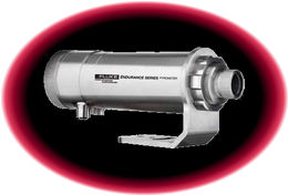
Endurance 2-Color Ratio & 1-Color Spot Pyrometers
E1R · E2R · E1M · E2M · E3M integrated heads · EF1R/EF2R/EF1M/EF2M fiber-optic — metals, glass, plastics, and furnace service 50 to 3200 °C
▼
2-color ratio principle (E1R, E2R) — simultaneous measurement at two wavelengths with common-mode attenuation cancellation; reads accurately through dust, steam, partial obscuration, and dirty optics; E1R (1.0 µm, 2-color mode 600–1800 °C D:S 100:1 / single-color 550–1800 °C 100:1; E1RH shortwave variant 1000–3200 °C D:S 150:1); E2R (1.6 µm, 250–1200 °C D:S 75:1); accuracy ±(0.5% Tmeas +2 °C), repeatability ±(0.3% Tmeas +1 °C); response 10–20 ms (95%)
Single-color metals — E1M · E2M · E3M — E1M (1.0 µm, 400–1740 °C D:S 160:1; E1MH 540–3000 °C D:S 300:1); E2M (1.6 µm, 250–1100 °C / 250–1400 °C D:S 160:1; E2MH 450–2250 °C D:S 300:1); E3M (2.4 µm, 50–1000 °C D:S 100:1; E3MH 150–1800 °C D:S 300:1); accuracy to ±(0.3% Tmeas +1 °C), repeatability to ±(0.1% Tmeas +1 °C); 2 ms response (95%) on 1 µm/1.6 µm; digital resolution 0.1 °C / analog <0.03 °C 16-bit
Three sighting options — through-the-lens visual plus aiming aid — Laser through-the-lens (Class II 1 mW 650 nm), Video camera through-the-lens (integrated CMOS for remote visual confirmation), or LED through-the-lens (for laser-sensitive environments e.g. plastics extrusion); all three with simultaneous visual sighting; manual variable-focus lens options F0 (190–300 mm), F1 (300–600 mm), F2 (600 mm to ∞)
Fiber-optic variants — EF1R · EF2R · EF1M · EF2M — rugged non-contact pyrometer for tight-access, high-EMI, or extreme-ambient installations; EF1R/EF2R (2-color 1.0/1.6 µm) 250 to 3200 °C range; EF1M/EF2M (single-color 1.0/1.6 µm) 250 to 3000 °C; D:S 20:1 to 100:1 per fixed-focus lens option (F0/F1/F2); optional laser aiming (not on H variants or 22 m cables); fiber cables 1, 3, 6, 10, or 22 m in low-temp BL (NEMA-4, 200 °C max ambient, IP65) or high-temp BH (315 °C max ambient) with stainless-steel armor and PTFE coating
Industrial communications and I/O — on-board Ethernet with ASCII, video, and embedded HTTP webserver; Profinet and EtherNet/IP field-bus options; 0/4–20 mA isolated analog output (500 Ω max load); RS485 2-wire half-duplex networkable; programmable relay (48 V, 300 mA, <2 ms); analog input for emissivity / e-slope / background-temperature compensation; power 20–48 VDC or PoE
Ambient-temperature rating and cooling — IP65 / NEMA-4 rugged stainless-steel housing; 0–65 °C uncooled; 0–120 °C with air cooling; 0–175 °C with water-cooled housing (E-TJ accessory); 0–315 °C (599 °F) with ThermoJacket enclosure (E-TJ1) — among the highest ambient ratings in the industry
Dirty-window alarm, fail-safe alarm, and field configuration — unique dirty-window detection flags degraded optical path before measurement error accrues; fail-safe alarm on sensor health; Endurance software for remote configuration, monitoring, and field calibration; peak hold, valley hold, averaging signal processing; emissivity range 0.100–1.150; e-slope 0.850–1.150 for ratio models
4-year warranty — best-in-class — among the longest coverage of any industrial process pyrometer; supported by FPI's factory repair and NIST/DAkkS-traceable calibration certificate (E-CERT) and DAkkS certificate (EN-DAKKS-CERT, EN-DAKKS-CERT-ACP) as separate line items
Accessories for integration and scanning — fixed bracket (E-FB) and adjustable bracket (E-AB), pipe adapter (E-PA), adjustable pipe adapter (A-AP-A), right-angle mirror (E-RA), air-purge collar (E-AP), mounting nut (E-MN), mounting flange for sighting tubes (A-MF-ST) with stainless (A-ST-SS), ceramic (A-ST-CER), or carbon-steel 45° (A-ST-CS-45) 30.4 cm sighting tubes; SpotScan™ accessory (SSA/SSB) converts an Endurance spot pyrometer into a scanning head across a line for applications short of a full line scanner
Fluke Process Instruments — Endurance
View product line ›
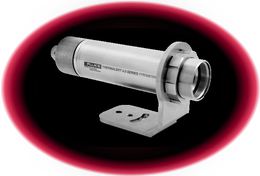
Thermalert 4.0 Single-Color Spot Pyrometers
LT · G5 · G7 · P3 · P7 · MT · HT · 1M · 2M · 3M · CO2/CO/NOX flame — −40 to 2300 °C across plastics, glass, metals, low-temp surfaces, and combustion
▼
Wide spectral coverage across a single platform — ten principal spectral models in a single compact IP65 / NEMA-4 stainless steel body (500 g): LT 8–14 µm for low-temperature general surfaces (LT-07, LT-15, LT-30, LT-50, LT-70, LTB-30 two-wire/no-laser, LTD-04 for extreme dust); G5 5 µm glass (G5-30, G5-70); G7 7.9 µm glass (G7-70); P3 3.43 µm plastics (P3-20); P7 7.9 µm thin-film plastics (P7-30); MT 3.9 µm medium-temp metals (MT-30, MT-70); HT 2.2 µm high-temp metals (HT-60); 1M 1 µm metals (1ML-150, 1MH-150); 2M 1.6 µm metals (2M-150); 3M 2.3 µm metals (3M-70); CO2/CO/NOX flame detection (CO2-30, CO-30, NOX-30)
Temperature range from −40 °C to 2300 °C — LTD-04 down to −20 °C; LT-50/LT-70 up to 1000 °C; 1MH-150 metals to 2300 °C; G5-70 glass to 2250 °C; HT-60 metals to 2000 °C; all with system accuracy ±1% of reading or ±1 °C (LT/G5/G7), ±(2 °C + 0.5% reading) for MT/HT/metals, ±(3 °C + 1% reading) for P3 and plastics, ±1–2% reading for flame variants; repeatability 0.3 °C (0.6 °F) or 0.3% reading on most, 1 °C (2 °F) on plastics and flame
Fast response for high-speed process control — 10 ms (95% value) on 1M/2M metals; 20 ms on 3M; 30 ms on LT-30/LTB-30; 60 ms on G5; 130 ms on most others; 150 ms on LT-07/LT-15/LTD-04 (lowest-cost plastic-lens variants)
Optical resolution D:S from 4:1 to 150:1 — LTD-04 D:S 4:1 close-focus; LT-30/LTB-30 33:1; LT-70/G5-70 70:1; HT-60 60:1; 1ML-150/1MH-150/2M-150 at D:S 150:1; focus distances SF0 1520 mm (60 in), SF2 1250 mm (49 in), SF4 500 mm (20 in) standard; close-focus CF0 50 mm, CF1 76 mm, CF2 200 mm; smallest measurement spot 1.1 mm (HT-60 CF1)
Back-panel electronics — four connector options — 2-Wire (12–28.8 VDC, 4–20 mA current loop, micro-USB for setup, alarm, emissivity via two rotary-code switches); 4-Wire M12 (PoE-powered Ethernet, EtherNet/IP, or PROFINET IO with installed fieldbus connector); 6-Wire pin-terminal-strip (RS485, 0–10 V, 0/4–20 mA, J/K thermocouple output, micro-USB); 12-Wire M16 (RS485, dual analog output 0/4–20 mA + 0–10 V, background-temperature compensation input, external reset/hold/laser-on trigger TTL, alarm output, emissivity analog input)
HART Protocol and Intrinsic-Safety options — HART communication variant (2-wire, 4–20 mA current loop, alarm output; no USB interface or laser on HART models); Intrinsically-Safe (-IS) variant for HART configuration with ATEX
II 2G Ex ib IIC T4 Gb (Gas); II 2D Ex ib IIIC T135 °C Db and IECEx Ex ib IIC T4 Gb / Ex ib IIIC T135 °C Db certifications for −20 °C ≤ Ta ≤ +80 °C; not available for plastic-lens sensors (LT-07, LT-15) or LTB-30Wide ambient rating and cooling accessories — stainless-steel IP65 / NEMA-4 body operates −20 to 85 °C (−4 to 185 °F) uncooled — what Fluke calls an “outstanding high maximum operating temperature”; air-cooled to 120 °C (248 °F) ambient; water-cooled to 175 °C (347 °F); ThermoJacket (A-TJ) enclosure to 315 °C / 599 °F
Laser sighting standard (with noted exceptions) — laser sighting on LT-30, LT-50, LT-70, G5-30, G5-70, G7-70, P7-30, MT-30, MT-70, HT-60, 1ML, 1MH, 2M, 3M; no laser sighting on LT-07, LT-15, LTB-30, LTD-04, P3, CO2, CO, NOX (or HART models); 2-wire devices require supplementary USB power to operate laser
Real-time background-temperature compensation and galvanic-isolated outputs — compensates for reflected thermal radiation from background sources (critical for low-emissivity metals, glass near hot surroundings); all analog outputs galvanically isolated; field-configurable peak/valley hold and averaging; DAkkS certificate option (T40-DAKKS-CERT / T40-DAKKS-CERT-ACP) separate line item; 2-year warranty
Fluke Process Instruments — Thermalert 4.0
View product line ›
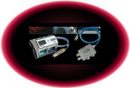
MI3 Compact Modular Sensors with Comm Box
Miniature sensing head plus comm box — LT · G5 · 1M · 2M · LTF fast · LTH high-ambient — plug-and-play multi-head with IS and Ethernet options
▼
Detachable-head modular architecture — industrial OEM pyrometer system comprising a miniature sensing head plus a separate communication box; Plug & Play automatic head detection; single comm box supports multiple heads (up to 4 on MCOMM modular DIN units, up to 8 heads via XXXMI3CONNBOX multi-channel interface extender); each head ships with one mounting nut and 1 m (3.3 ft) cable; cable extensions CB3 (3 m), CB8 (8 m), CB15 (15 m), CB30 (30 m) factory-configured at time of order
LT and G5 heads — low and mid temperature, 8–14 µm and 5 µm — 02LTS (−40 to 600 °C, D:S 2:1), 10LTS (−40 to 600 °C, D:S 10:1), 20LTS (0 to 1000 °C, D:S 22:1 typical / 21:1 guaranteed), 10LTF fast-response (0 to 1000 °C, 20 ms), 10LTH/20LTH high-ambient (to 180 °C ambient vs. standard 120 °C), 10G5S (250 to 1650 °C, 5 µm glass); ±(1% reading or 1 °C) accuracy; 130 ms standard response; Close Focus Lens accessory (XXXMI3ACCFL) for spot sizes to 0.5 mm
1M and 2M heads — laser-sighted short-wave metals — 1001MSF1 / 1001MSF3 (1 µm, 500–1800 °C, D:S 100:1, 200 mm or 2200 mm focus, 10 ms response, 1 m cable); 1002MSF1 / 1002MSF3 (1.6 µm, 250–1400 °C, D:S 100:1, 200 mm or 2200 mm focus, 10 ms, 1 m cable); ±(0.5% reading +2 °C) accuracy; ±(0.25% reading +1 °C) repeatability; laser auto-switches off at 65 °C head ambient
Rugged industrial head cable — PUR jacket, silicone and halogen-free, resistant to oil, bases, and acids; IP65 (NEMA-4) environmental rating on all heads; storage −20 to 120 °C (standard) or −20 to 180 °C (LTH)
Cooling accessories — Water-Cooled Housing + Air-Purge Collar + Teflon high-temperature cable (WS / WSCB3 / WSCB8 / WSCB15) for 1M/2M heads above 120 °C ambient; Air Cooling Jacket XXXMIACCJ (0.8 m) or XXXMIACCJ1 (2.8 m) for LT/G5 heads to 200 °C; Air Purge accessory (XXXMIACAJ or XXXMI3100AP); Protective Window accessories
Intrinsically-Safe (IS) heads with dedicated Ex-PSU — MI3…IS variant carries ATEX
II 2G Ex ib IIC T4 Gb (gas) and II 2D Ex ib IIIC T135 °C Db (dust); stainless-steel construction; requires separate MI3ACIS Ex-Power Supply Box rated II (2)G [Ex ib Gb] IIB / II (2)D [Ex ib Db] IIIC — supports up to 2 IS heads per Ex-PSU with 5 m cable to comm boxComm-box protocol suite — IP65 metal cast-zinc enclosure — RAYMI3COMM (USB 2.0 basic); RAYMI3COMM4 (USB + RS485); RAYMI3COMMM (USB + Modbus); RAYMI3COMME (USB + Ethernet with built-in HTTP server, M12 connector); RAYMI3COMMP1 (USB + Profibus M12) or RAYMI3COMMP2 (USB + Profibus 9-pin D-sub); RAYMI3COMMPN (USB + Profinet M12); "I" suffix indicates factory-installed head before shipment (not available with IS variants)
Modular DIN-rail comm boxes — MCOMM family — RAYMI3MCOMM 3TE or 4TE box with USB + RS485; MCOMMM (USB + Modbus); MCOMME (USB + Ethernet HTTP); MCOMMP (USB + Profibus); MCOMMPN (USB + Profinet); MCOMMA (USB + 4 galvanically-isolated analog outputs); MCOMMN headless 3TE box with USB + alarm relay only (no display or RS485)
Networkable OEM head option — sensing head configured for direct integration into customer control systems without the separate comm box; for deep embedding into industrial equipment where comm-box overhead is unacceptable
Raytek — MI3
View product line ›
Line Scanners & Thermal Imagers — Fluke Process Instruments · Raytek
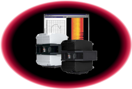
MP Shortwave Line Scanners (1M · 2M · 3M)
MP150 and MP300 platforms — 150 and 300 Hz scanning for hot-metal rolling, forging, galvanizing, and continuous casting
▼
Real-time thermal line scanning for high-temperature metals — up to 1024 measurement points per scan line; 150 Hz scan rate (MP150 models) or 300 Hz (MP300 models); field of view 90°; built-in line laser for accurate alignment; focus 1.52 m (4.9 ft) standard with custom focus available
Four shortwave spectral bands covering metals service — 1ML (1 µm, MP150: 600–1500 °C / MP300: 650–1500 °C); 1MH (1 µm, 700–1800 °C); 2M (1.6 µm, MP150: 350–1500 °C / MP300: 400–1500 °C); 3M (2.4 µm, MP150: 200–1500 °C / MP300: 250–1500 °C); D:S 200:1 measurement resolution, 600:1 hot-spot detection
Accuracy and repeatability — ±0.5% or ±3 °C accuracy (whichever is greater) across entire ambient operating range; repeatability ±2 °C (4 °F); response time 2–20 ms depending on spectral range; temperature limits 0 °C lower bound and 3000 °C (5432 °F) upper bound per model
Rugged aluminum-cast IP65 waterproof enclosure — high-quality brushless scan motor rated MTBF 40,000 hours; built-in air purge keeps window clear of dirt and condensation; built-in water cooling for operation to 180 °C (356 °F) ambient; internal-heater option for operation down to −40 °C ambient
Four data-point configurations selectable per scan rate — 256 points per line (up to 150 Hz or 300 Hz); 512 points per line (up to 80 Hz or 160 Hz); 1024 points per line (up to 40 Hz or 80 Hz); signal processing — max, min, average, peak/valley hold, alarm setpoints; further signal-processing functions configurable in software
On-board communications — PC-independent operation — Ethernet TCP/IP 10/100 Mbit/s built-in; 3 user-configurable 0/4–20 mA isolated analog current outputs (max load 500 Ω); relay alarm output 30 V / 1 A; RS485 full-duplex non-addressable serial; I/O module support for up to 10 independent sectors/zones per scanner, operating without PC
Two connector architectures — integrated M12 or Quick Connector — M12 plug with 7.5 m (25 ft) Ethernet + power cable with RJ45 (180 °C rated cable standard); Quick Connector variant (1M/2M/3M models only, similar to ScanIR3) with separate Main Processor Box (A-MP-BOX-QUICKCON), Enclosure and Base (A-MP-ENC-QUICKCON), optional Insulation Shield (A-MP-ENC-INSU) or Water-Cooled Shield (A-MP-ENC-WCS)
Factory and field accessories — Adjustable Mounting Base (A-MP-RMB); Power supply 240 VAC / 24 VDC 1.3 A DIN-rail (A-PS-DIN-24V); Linescanner thermostat (A-MP-THERM); Quick-connector system cable (A-CB-QUICKCON-XX); manufacturer's calibration certificate based on NIST/DAkkS certified probes (MPCERT-1) available as separate line item
Applications — hot-metal rolling mills, continuous casting, forging, galvanizing bath monitoring, aluminum extrusion, hot-strip rolling, plate mills — anywhere shortwave wavelengths are required to read through furnace atmospheres and hot-metal surface effects at scan rates beyond a single-point pyrometer; 2-year warranty
Fluke Process Instruments — MP Linescanner
View product line ›
MP150 Multi-Spectral Line Scanners with Tailored Application Software
MP150 platform — LT · MT · G5 · P30 · P31 · HR spectral models — paper, film, coil, glass, thermoforming, and cement-kiln service — with application-specific MP-SYS software
▼
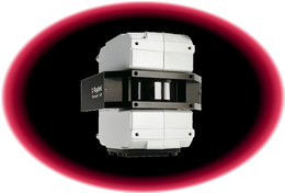
Raytek MP150 — flagship multi-spectral line scanner in current production — Raytek's flagship linescanner serving paper, film, coil coating, extrusion, glass, thermoforming, and cement-kiln monitoring across tens of thousands of field installations worldwide; six spectral models (LT · MT · G5 · P30 · P31 · HR) and five application-specific MP-SYS software packages cover the target industries. Predecessor Raytek MP50 installations remain fully supported in service, with MP150 as the direct upgrade path — preserving the MP50 spectral-model footprint while adding 1024 scan points, higher scan rate, and modern Ethernet + fieldbus communications.
Multi-spectral line scanner family for process-monitoring across web, coating, extrusion, glass, thermoforming, and kiln industries — 150 Hz scan rate, 512 data points standard (up to 80 Hz) / 256 points (up to 150 Hz); enhanced data-point configuration — 1024 points (up to 40 Hz) / 512 points (up to 80 Hz) / 256 points (up to 150 Hz); RJ-45 Ethernet communication; on-board line laser for alignment
Six spectral models matched to service material and temperature — LT (3–5 µm, 20–350 °C, D:S 170:1) for paper, film, paint, low-temp coating; MT (3.9 µm, 100–800 °C, D:S 170:1) medium-temp metals and coatings; G5 (5 µm, 100–950 °C, D:S 170:1) general glass; P30 (3.43 µm, 30–250 °C, D:S 33:1) thin-film plastics at lower temperatures; P31 (3.43 µm, 100–350 °C, D:S 75:1) thin-film plastics at higher temperatures; HR (3.5–4 µm, 100–650 °C, D:S 170:1) cement-kiln shell monitoring (basis for CS400 kiln system with HRR1 variant)
Accuracy and repeatability — ±2 °C (LT), ±0.5% or ±3 °C (MT/G5/HR, whichever greater), ±3 °C (P30/P31); repeatability ±1 °C (2 °F) across full ambient operating range; hot-spot detection 510:1 (LT/MT/G5/HR) or 100:1/225:1 (P30/P31)
Rugged aluminum-cast IP65 housing — brushless scan motor MTBF 40,000 h; integrated air purge keeps window clear; built-in water cooling for up to 180 °C (356 °F) ambient; 7.5 m (25 ft) Ethernet + power cable rated 180 °C included
Three configurable analog outputs and relay alarm — PC-independent — 3 user-configurable 0/4–20 mA isolated outputs (max load 500 Ω); 30 V / 1 A relay contact alarm; I/O module support for up to 10 independent zones/sectors; RS485 full-duplex serial; Ethernet TCP/IP 10/100 Mbit/s; emissivity 0.1–1.0 digitally adjustable
MP-SYS-ES Sheet Extrusion software — general-purpose web-processing monitoring for most web lines — coating, laminating, and film extrusion; zone-alarm logic and historical trend storage for process tuning and QC reporting
MP-SYS-EC Extrusion Coating software — dedicated extrusion-coating-process monitor with tailored zone architecture for the coat-substrate-oven-cooling web sequence
MP-SYS-TF Thermoforming software — dedicated cut-sheet thermoforming monitor with sheet-sag prediction and oven-zone feedback for part-quality consistency
MP-SYS-GS Glass software — dedicated secondary-glass monitor for bending, forming, annealing, and tempering lines; alarm-trigger logic tuned for glass surface temperature profiles
MP-SYS-GSLE Low-E Glass software — monitor for glass coated on one side with a low-emissivity coating; the asymmetric emissivity problem requires specialized sensing — package includes MP-SYS-GS software foundation, a specialized MI3 sensor calibrated for low-E glass, air-purge jacket, and PC connection kit; specific to Low-E architectural and automotive glass manufacturing
Options and accessories — Adjustable Mounting Base (A-MP-RMB); A-PS-DIN-24V 240 VAC/24 VDC 1.3 A power supply; A-MP-THERM thermostat; manufacturer's NIST/DAkkS-traceable calibration certificate XXXTMP150CERT as separate line item; A-MP-ENC stainless-steel protective housing; internal-heater option (HRR1 variant) for kiln installations
Raytek — MP150 Linescanner
View product line ›
ThermoView TV30 Fixed Thermal Imagers
TV33 (320×240) and TV36 (640×480) · SA standalone edge-analytics or GE GigE with ThermoView software — −10 to 1300 °C LWIR process monitoring
▼
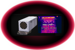
Rugged fixed LWIR thermal imager for continuous industrial monitoring — uncooled focal-plane-array detector, 8–14 µm spectral band, −10 to 1300 °C (14 to 2372 °F) measuring range; ±2 °C or ±2% (reading) accuracy (whichever greater); emissivity correction 0.10–1.00; compact 50 × 50 × 142 mm (1.96 × 1.96 × 5.58″) body; IP67 environmental rating for harsh-environment survival
Two resolutions matched to application — TV33 at 320 × 240 (76,800 pixels) for standard process monitoring; TV36 at 640 × 480 (307,200 pixels) for high-definition inspection, back-light, and critical-asset applications; 9 Hz or 60 Hz frame rate per model (60 Hz requires end-user statement for export compliance)
Three lens options with motorized focus — 30° × 22° standard (focus 220 mm to ∞); 22° × 16° telephoto (focus 190 mm to ∞); 48° × 36° wide-angle (focus 100 mm to ∞); 300 mm motorized remote focus; field-of-view calculating software ("Spot Size Calculator") available from manufacturer
SA (standalone) model — edge-based on-board analytics — monitor temperatures and configure multiple areas of interest without a PC; full analytics accessed through a web browser; supported protocols MQTT, OPC UA, TCP, DHCP, UDP, mDNS (Bonjour); interface directly to PLCs or other devices using multiple field-bus protocols or discrete I/O; reduces installation footprint and eliminates dependence on vulnerable computer equipment in severe environments
GE (GigE) model — PC-based with ThermoView software for advanced capability — GigE industrial-camera protocol enables the full ThermoView software analytics suite beyond what the SA's on-board analytics provide
ThermoView software — reference-baseline and multi-zone analytics — set a standard "good" reference temperature and compare new imaging to display deviation; control and review multiple data points for each individual pixel; set custom-shaped AOI zones including overlapping zones, each with independent emissivity, alarm, and trigger settings (including target-displacement triggering)
ThermoView software — trend analysis, recording, and export — powerful real-time trends and analysis trends with statistics; image and trend recorders with pre-trigger buffer support; frames aggregation and frame-rate reduction; CSV and clipboard export of temperature data; snapshot capture with alarm-based triggering
ThermoView software — automation, alarms, and process integration — automation mode with conditions, triggers, and alarm/signal logic; DAQ configuration to WAGO 750-352 fieldbus coupler and Modbus TCP server; image subtraction by trigger; image and trend recorders with trigger-initiated recording; camera shutter control; alarm-notification emails; multi-image composition panels; project-loading automation; password-lock security
Electrical and mounting — 24 VDC ± 20% or Power over Ethernet (IEEE 802.3at); operating ambient −10 to 50 °C (14 to 122 °F); storage −20 to 70 °C; shock IEC 60068-2-27 (50 g / 6 ms / 3 axes); vibration IEC 60068-2-26 (3 g / 11–200 Hz); accessories include air-purge collar, water-cooling jacket, and outdoor enclosure; 2-year warranty
Fluke Process Instruments — ThermoView TV30
View product line ›
Portable & Basic OEM Sensors — Raytek
Raynger 3i Plus Portable Handheld Pyrometer
1M and 2M high-temperature handheld thermometer — 400 to 3000 °C, D:S 250:1, dual laser, Red Dot sighting, Bluetooth and scope options
▼
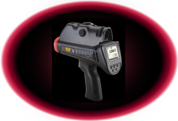
High-temperature handheld pyrometer for hot-target industrial work — ergonomic comfort-grip body; 1 m (3.2 ft) drop-rated rugged construction; 2.5 Ah rechargeable Li-ion battery with 24-hour operational cycle; stronger, simpler, safer field-measurement platform for process-monitoring, fault-preview, and hot-equipment inspection work
Two shortwave spectral models — RAYR3IPLUS 1M (1 µm dual laser EN60825 Class 2 / FDA Class II, 700 to 3000 °C / 1292 to 5432 °F, D:S 250:1, USB); RAYR3IPLUS 2M (1.6 µm dual laser, 400 to 2000 °C / 752 to 3632 °F, D:S 250:1, USB)
Dual-laser aiming with Red Dot sighting for red-hot targets — dual laser for precise measurement-target definition; Red Dot sighting technology for accurate targeting when high-temperature targets are not visible under laser sighting alone (glowing incandescent surfaces); optional scope sight (SC) for aiming against red-hot backgrounds
"Red Nose" operator-safety warning — heat-resistant warning detector at the sensor nose alarms operator before the instrument approaches temperatures that could damage the thermometer or burn the user; enables confident approach to incandescent targets
Bluetooth and USB data transfer — Bluetooth 4.0 optional (certified for EU, US, SA, Canada, Korea, India, and Brasil); NBT no-Bluetooth variant for markets where Bluetooth is not approved; DataTemp 3i Plus Windows PC software for real-time graphic temperature display, logging, analysis, and trending; mobile app for smartphone data transfer, on-site reporting, and collaboration
Can operate as a temporary online thermometer — field-mountable usage mode with real-time monitoring through PC software or mobile app; useful for spot-monitoring process excursions without deploying a fixed pyrometer
Standard kit — Raynger 3i Plus, carrying case, neck strap, 1× 2.5 Ah Li-ion battery, 110 V / 60 Hz and 220 V / 50 Hz mini-USB port adaptors, mini-USB-to-DC jack converter for charging battery separately, USB-to-mini-USB computer connection cable (1.5 m / 4.9 ft), operator's manual; NIST-traceable calibration available as separate line item (part 2132558)
Raytek — Raynger 3i Plus
View product line ›
CM / CI / GP Basic OEM Sensors
Raytek CM (−20 to 500 °C 13:1) · CI (0 to 500 °C 4:1) · GP (−18 to 538 °C 35:1 or 45:1) — stainless steel threaded sensors with TC or voltage output
▼
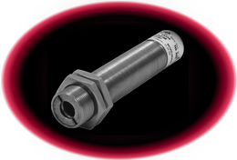
CM basic OEM sensor — 1-color 8–14 µm LWIR — −20 to 500 °C (−4 to 932 °F); D:S 13:1 at focal point (90% energy), 9:1 far-field; 150 ms response (95%); ±1.5% of reading or ±2 °C accuracy (whichever greater, at 23 °C ±5 °C ambient, ε = 0.95); repeatability ±0.5% reading or ±0.5 °C; stainless-steel IP65 / NEMA-4 housing, 70 °C ambient without cooling; ¾"-16UNF standard thread or M18×1 metric (M suffix); 1 m (3.3 ft) or 3 m (9.8 ft) cable; scaleable 0–5 V (J suffix), Type J thermocouple (J), or Type K thermocouple (K) output; RS232 digital interface for setup/monitoring via DataTemp Multidrop software; 24 VDC alarm output; sensor health LED
CI basic OEM sensor (Americas / APAC only) — 1-color 7.6–18 µm LWIR — cost-optimized OEM pyrometer in stainless-steel IP65 housing; D:S 4:1 at focal point, 350 ms response; two temperature models — CI1A/CI2A/CI3A (0 to 350 °C / 32 to 662 °F, ±3 °C accuracy 0–115 °C then larger of ±5%); CI1B/CI2B/CI3B (30 to 500 °C / 86 to 932 °F, larger of ±2% or ±3 °C accuracy)
CI output options matched to standard controller inputs — J-type thermocouple (CI1), K-type thermocouple (CI2), or voltage 10 mV/°C linear 0–5 V (CI3); 50 Ω output impedance matches thermocouple break-protection circuitry in most industrial controllers, displays, and transmitters — drop-in upgrade from contact TC probes; fixed 0.95 emissivity
CI cable and cooling options — 1 m (3.3 ft) standard cable, 3 m (10 ft) standard-temp 105 °C (10L suffix), 3 m high-temp 260 °C (10H), 15 m (50 ft) standard-temp (50L) or high-temp (50H); 12–24 VDC at 20 mA power draw; ¾"-16UNF or M18×1 thread; 70 °C ambient uncooled, 260 °C with water cooling
GP basic OEM sensor (Americas / APAC only) — 1-color 8–14 µm LWIR with monitor — −18 to 538 °C (0 to 1000 °F); two variants — GPR (without laser sighting; Standard Focus D:S 35:1 or Close Focus D:S 30:1 with 3 mm spot at 76 mm) and GPS (with laser sighting; Standard Focus D:S 50:1 or Close Focus D:S 45:1 with 4.5 mm spot at 200 mm); 300 ms response
GP accessories and monitor requirement — Air/Water-coolable housing with integrated air-purge collar (W suffix) for ambients above 65 °C (150 °F); 7-pin DIN connector option (C suffix on GPR) for high-vibration environments using XXXCB25 or XXXCB50 cables; GPC or GPCM monitor required separately (not included); GPS kit includes 4 m cable to laser switch box and 8 m cable from switch box to GPC monitor; NIST traceable calibration via part 2132558 as separate line item
Raytek — CM / CI / GP
View product line ›
Kiln Shell Monitoring Systems — Fluke Process Instruments
CS400 Rotating Kiln Shell Monitoring System
CS401 · CS402 · CS403 · CS404 single through four-scanner systems — one-brick hot-spot resolution for cement, lime, metals, and waste-incineration rotary kilns
▼
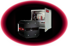
Complete integrated thermal-imaging system for rotary kilns — cement kilns, lime kilns, metals and chemical processing kilns, and waste-incineration kilns; continuous infrared monitoring that pictures every brick in the kiln in real-time to prevent costly shutdowns and extend refractory life; core sensor is the MP150HRR1 linescanner — the HR spectral variant (3.5–4 µm) with internal heater and 1024 scan points per line, tuned for kiln-shell temperature and geometry
One-brick hot-spot detection and failsafe alarm — maps entire kiln surface and displays in real-time thermogram format; hot-spot detection at one-brick resolution including in shadowed areas; fail-safe hot-spot alarm outputs (PC-independent); on-board Ethernet TCP/IP; OPC interface to plant process-control systems; all data, alarms, and events stored and accessible in one common environment with multiple security levels
Four scanner-count system packages — CS401-MP150-KIT single-scanner system (1 × MP150HRR1 + A-MP-ENC stainless-steel protective housing + S-CS-CONBOX field connection box); CS402-MP150-KIT-2 dual-scanner system; CS402-MP150-KIT-3 three-scanner system (CS403 family); CS402-MP150-KIT-4 four-scanner system (CS404 family) — multi-scanner configurations cover long kilns or kilns with significant shadow obstructions
Central hardware kit — CS400-HW-KIT-BASIC provides the fiber-optic converter housing XXXHSFICBOX for control-room installation plus the position-indicator kit (A-CS-PI-KIT) with junction box; enables reliable signal transport from kiln-area scanners to the control room
Software licensing tiers — CS400-SW-STD Standard license (1 client); CS400-SW-ADV Advanced license (1 client, includes full 3D moving-view of kiln and refractory-management history); CS400-SW-CL additional Client License; CS400-SW-ADV-UPG Standard-to-Advanced upgrade; CS400-SW-CS210-UPG and CS400-SW-CS210-ADV legacy CS210-to-CS400 upgrades (scanner serial number required; I/O upgrade also required when installed on CS210)
Burning-Zone Monitor kit (A-CS-BZ-EN-KIT-485) — integrates a two-color Endurance ratio pyrometer (600–1800 °C) inside a ThermoJacket housing with blast-gate quartz window, 30 cm stainless sighting tube, adjustable pipe adapter, adjustable mounting base, and air-flow/pressure regulator; "sees through" combustion gases to monitor the critical burning zone temperature alongside the kiln shell; requires A-CS-CONV-ETH485 Serial-to-Ethernet converter (separate line item)
Shadow-Monitoring kit (A-CS-SM-KIT-485) — supplements the primary linescanner in shadowed zones where kiln tires, buildings, or utility poles obscure the scan path; includes RAYMI310LTH high-ambient sensor (−40 to 600 °C) with 8 m high-temperature cable and stainless-steel air-purge jacket; data seamlessly integrated into the main thermogram; requires serial-Ethernet converter
Tire-Slip Monitoring kit (A-CS-TSM-KIT-485) — records mechanical slip between kiln drive tires and the shell; TSM remote control box plus 3 position indicators; alarm thresholds configurable; extensive historical data analysis for predictive maintenance; requires serial-Ethernet converter
I/O modules and plant-level integration — optional digital-input and digital-output modules plus analog outputs for fan control and hot/cold alarms; enables closed-loop process response to kiln-shell thermal events without separate PLC programming
Fluke Process Instruments — CS400
View product line ›
Legacy Migration Reference — Ircon
Ircon Legacy Migration Reference
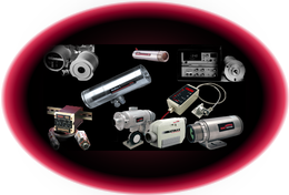
Modline 7 · Modline 6 · Modline 5 · Modline 4 · Modline 3 · Maxline · SR-Series · Mirage · Ultimax · InfraRail · ScanIR — supported in the field, replacement path to current Fluke Process Instruments and Raytek lines
▼
2-color (ratio) preservation rule — top priority in migration — all legacy Ircon 2-color / ratio pyrometers (Modline 5 MR variants, Modline 6 MR fiber-optic variants, 2-color Maxline) must migrate to a 2-color successor: integrated heads to Endurance E1R (1.0 µm, 600–1800 °C / E1RH to 3200 °C) or E2R (1.6 µm, 250–1200 °C); fiber-optic heads to Endurance Fiber-Optic EF1R (1.0 µm) or EF2R (1.6 µm) to 3200 °C. Single-color successors cannot preserve the ratio principle or its common-mode attenuation cancellation through dust, steam, partial obscuration, and dirty optics.
Modline 5 single-color → Endurance (integrated-head path) — Modline 5 integrated single-color pyrometers migrate to the Endurance Series (E1M · E2M · E3M), which preserves and exceeds the Modline 5's optical-resolution and ambient-temperature envelope while adding Ethernet / Profinet / EtherNet/IP communications, video-through-the-lens sighting, ThermoJacket to 315 °C, and the 4-year warranty
Modline 6 single-color → Endurance Fiber-Optic (fiber-optic path) — Modline 6 single-color fiber-optic installations migrate to Endurance Fiber-Optic (EF1M · EF2M), retaining the fiber-decoupled electronics-box architecture for tight-access and high-EMI environments and adding the same communications suite as the integrated Endurance
Modline 3, Modline 4, Maxline, and other legacy single-color Modline series → Thermalert 4.0 — Thermalert 4.0 covers the full Modline single-color spectral inventory (LT, MT, HT, 1M, 2M, 3M, G5, G7, P3, P7, flame CO2/CO/NOX) with modern connector suites (2-wire, 4-wire M12, 6-wire, 12-wire M16; Ethernet, EtherNet/IP, Profinet, HART, RS485); HART and Intrinsically-Safe options available for field installations previously served by legacy Modline HART variants. Exception: any 2-color / ratio variants within this legacy group (e.g., Maxline 2-color) migrate to Endurance E1R/E2R or EF1R/EF2R per rule 1 above, not to Thermalert 4.0
ScanIR → MP150 line scanner — legacy ScanIR systems migrate to the Raytek MP150 multi-spectral line scanner family, with MP150 spectral model selection matched to the original ScanIR service (LT, MT, G5, P30, P31, HR); ScanIR cement-kiln-monitoring installations migrate to MP150HRR1 within the CS400 Rotating Kiln Shell Monitoring System — including integrated burning-zone, shadow-monitoring, and tire-slip-monitoring accessory kits
Modline 7 → Endurance — legacy Modline 7 integrated pyrometers migrate to the Endurance Series (E1M / E2M / E3M single-color; E1R / E2R for any 2-color variant per rule 1 above), gaining the modern communications suite, video-through-the-lens sighting, and 4-year warranty
SR-Series (2-color / ratio) → Endurance E1R / E2R — the SR-Series ratio pyrometers follow the 2-color preservation rule: integrated heads to Endurance E1R / E2R, fiber-optic to EF1R / EF2R — never a single-color successor
Mirage Series → Thermalert 4.0 or Endurance — legacy Mirage single-color pyrometers migrate to Thermalert 4.0 for a direct spectral match, or to the Endurance Series where higher optical resolution and the full communications suite are required
Ultimax portable → Raytek Raynger 3i Plus — legacy Ircon Ultimax handheld single-color units migrate to the Raytek Raynger 3i Plus high-temperature portable (1M / 2M)
InfraRail continuous / rail monitoring → Raytek Mi3 multi-head or Thermalert 4.0 with GP Monitor — legacy InfraRail multi-point monitoring installations migrate to a Raytek Mi3 multi-head arrangement (compact sensing heads + comm box) or to Thermalert 4.0 spot pyrometers aggregated through a GP Monitor display
Migration adapter kits available for in-place retrofit — E-M5WJAK adapter kit mounts an Endurance pyrometer into the existing WJ-5 water-jacket footprint left by a Modline 5 removal, avoiding re-piping and re-bracketing; E-M5PKMC cable-kit adapter provides Endurance-to-Modline-5 cable-interface continuity during transition periods; A-MF-MOD mounting flange adapts a Thermalert 4.0 installation to a Modline footprint for direct head-for-head replacement
Field support — existing installations — Prater supports existing Modline, Maxline, and ScanIR installations in service; replacement quotes and migration planning available on request; in-place retrofit guidance and adapter-kit sourcing included; when legacy systems reach end-of-serviceable-life or parts availability, the migration paths above provide drop-in or low-disruption replacement routes
Ircon — legacy / migration reference
View product line ›
Legacy Migration Reference — Raytek
Raytek Legacy Migration Reference
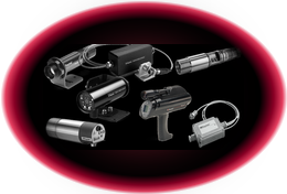
Marathon MM / MR / MA · Marathon FA / FR fiber-optic · Thermalert XR / TX / SX · T3Plus · compact MI · Raynger 3i · MP50 / ScanIR2 line scanners · CS100 kiln · TIP450 · legacy ThermoView — supported in the field, replacement path to current Raytek and Fluke Process Instruments lines
▼
2-color (ratio) preservation rule — legacy Raytek 2-color / ratio units (Marathon MR ratio variants) migrate to a 2-color successor: Endurance E1R / E2R integrated or EF1R / EF2R fiber-optic — never a single-color successor, preserving ratio measurement through dust, steam, and partial obscuration
Marathon MM / MA → Endurance — Marathon single-color spot pyrometers (MM LT / MT / G5, MM 1M / 2M / 3M, and the MA) migrate to the Endurance Series (E1M · E2M · E3M), matched on spectral band and optics; high-temperature metals units keep their short-wavelength (1 / 1.6 / 2.4 µm) band on the Endurance 1M / 2M / 3M
Marathon MR → Endurance E1R / E2R — the two-color (ratio) Marathon MR migrates to the Endurance E1R / E2R ratio pyrometer, holding ratio measurement through dust, scale, and an underfilled spot per the 2-color rule above
Marathon FA / FR fiber-optic → Endurance Fiber-Optic — the fiber-optic Marathons migrate to Endurance Fiber-Optic, preserving principle: single-color FA1 / FA1G → EF1M / EF2M, and the two-color FR → EF1R / EF2R, retaining the fiber-decoupled electronics-box architecture for tight-access and high-EMI zones
Thermalert XR / TX / SX → Thermalert 4.0 — legacy XR, TX, and SX single-color pyrometers migrate to Thermalert 4.0, matched to the original spectral model (LT · MT · HT · 1M · 2M · 3M · G5), with modern connector and communications suites (Ethernet, EtherNet/IP, Profinet, HART); the TX intrinsic-safety rating carries across on the Thermalert 4.0 IS interface option
T3Plus thin-film monitor → Thermalert 4.0 — the discontinued T3Plus plastics-film monitor (3.43 µm) migrates to Thermalert 4.0 on its plastics-film (P3) range
Compact MI → Raytek Mi3 — the discontinued two-piece compact MI (RAYMI — MID / MIC / MIH; LT 8–14 µm, 10:1 / 22:1, −40 to 600 °C) migrates to the current Raytek Mi3 compact modular sensor, which keeps the same miniature-sensing-head-plus-separate-electronics-box architecture; specify the Mi3 LT head and matched optics for a like-for-like replacement
MP50 / ScanIR2 line scanners → MP150 + MP-SYS — discontinued MP50 / ScanIR2 line scanners migrate to the MP150 platform with MP-SYS application software (TF150 thermoforming · GS150 / GS150-LE glass · ES150 / EC150 web); the CS100 rotary-kiln-shell system migrates to the CS400 on the MP150HR platform, and the TIP450 wallboard imager to the MP150-based TIP900
Legacy ThermoView imager → ThermoView TV30 — discontinued ThermoView thermal imagers migrate to the ThermoView TV30 fixed thermal imager (TV33 / TV36), with SA standalone edge-analytics or GigE + ThermoView software
Raytek 3i portable → Raynger 3i Plus — legacy 3i handheld pyrometers migrate to the current Raynger 3i Plus high-temperature portable (1M / 2M)
Field support & full cross-reference — Prater supports existing Raytek installations in service and provides discontinued-model replacement quotes and migration planning on request; the complete discontinued-model → current-replacement cross-reference table lives on the Raytek legacy series page
Raytek — legacy / migration reference
View product line ›
FAQ: IR pyrometers & thermal imagers
How do IR sensors work?
Every object above absolute zero radiates energy, and a measurable share of it falls in the infrared band of the electromagnetic spectrum. An IR sensor — a/k/a a pyrometer, infrared thermometer, or thermal imager (across a field of view) — collects that radiation through a lens, optically filters it to a specific wavelength range (its spectral response), and focuses it on a sensing element. The detector converts the radiated energy into an electrical signal proportional to the target's temperature, which is then scaled and sent to a local display or a control system. Because it reads from a distance with nothing touching the target, an IR sensor measures surfaces a thermocouple or RTD cannot — moving webs and rolls, energized equipment, and hot or hard-to-reach objects. Two setup decisions govern accuracy: choosing the right spectral response for the material, and entering the correct emissivity. Emissivity is the fraction of energy a surface radiates compared with a perfect blackbody (the standard of which emissivity is based) at the same temperature. On an opaque surface the remainder is ambient heat sources adding to the measured energy via reflections onto the surface, or in some cases transmissions from behind the material. So emissivity plus reflectivity plus transmission (if any) equals one, although it is further affected by surface finish, oxidation, and wavelength choice — which is why it has to be specified and set deliberately, not left at a default.
Which spectral response (a/k/a wavelength) should I use?
Each spectral range reads surface temperature based on the material. Match the wavelength to the target:
- 8 to 14 µm — plastics (thick/opaque), paper, painted and organic surfaces; general-purpose for low to medium temperatures.
- 7.9 µm — thin polyester films (PET, PETG), polyurethane, and other plastic films that are transparent at 8–14 µm but absorb strongly at this wavelength.
- 5 µm — glass surface temperature. Glass is opaque at 5 µm, so the reading represents the surface rather than energy transmitted from behind it. Used on flat glass, container glass, and similar.
- 3.43 µm — thin polyethylene and polypropylene films; polyolefins that transmit at longer wavelengths but absorb at 3.43 µm.
- 1 to 2 µm (typically 1.0, 1.6, and 2.2 µm) — high-temperature metals, molten metals, induction-heated parts, and semiconductors. Short wavelengths reduce the temperature error caused by emissivity uncertainty and work well at high target temperatures, where signal strength at these wavelengths is strong.
Picking the wrong wavelength is the most common cause of a reading that looks wrong no matter how the emissivity is set — for example, sighting a thin film with an 8–14 µm sensor and unknowingly reading the roll behind it.
How do you calibrate an IR sensor?
There are two distinct exercises, and people use "calibrate" for both. The first is dialing in emissivity to a known material temperature. If a surface thermocouple/RTD reading is possible, adjust the pyrometer's emissivity setting up or down until the IR reading matches. For a reference temperature, three field methods work: (A) — a thermocouple or RTD touching the material at process temperature — (B) — coat a patch of the target with a material of known high emissivity, such as flat black high-temperature paint, read the patch, then adjust emissivity on the bare surface to match — (C) apply Kapton® tape, which has a known emissivity of about 0.95 in the 8–14 µm range, onto a material appropriate for this wavelength range to a section of web material at process temperature — preset the pyrometer to 0.95, read the tape, then adjust the emissivity setting while looking at the bare material after the tape section has passed. The second use of "calibrate" is verification against a blackbody calibration source — a lab device with a known, traceable emissivity of 1.0. The blackbody is, in fact, what the emissivity scale is referenced to. NIST- and DAkkS probe based calibration certificates are available as a line item on any Fluke Process Instruments and Raytek sensor and should be renewed on the interval your quality system requires.
How do you mount an IR sensor?
Typical mounts include single-axis "L" brackets, two-axis "double-L" brackets, and swivel or flange-mount accessories. Beyond the hardware, three things matter: for single-color pyrometers aim the sensor so that the target fully fills the measured spot at the working distance (see distance-to-spot, below), keep the line of sight clear of steam, dust, and obstructions (2-color can tolerate these). Where the optics face a dirty or hot process, add an air purge to keep the lens clean and a cooling accessory to keep the housing in range. Avoid sighting through a window unless the window material is transparent at the sensor's wavelength and set the window transmissivity value into the pyrometer interface.
Can IR sensors withstand high heat?
The sensor's electronics must stay within their rated ambient temperature. That limit varies by series and detector type, but as a guide: most fixed sensors are rated roughly 0 to 65 °C uncooled, with the longwave Thermalert 4.0 spot sensors among the highest in the category at −20 to +85 °C uncooled. Past that, cooling accessories extend the envelope:
- With an air-cooling jacket and clean instrument air — often to about 120 °C ambient.
- With a water-cooled housing — often to about 175 °C ambient.
- With a water-cooled housing plus an air-purged over-jacket (for example the ThermoJacket) — often to about 315 °C ambient.
The target temperature the sensor reads is a separate spec — pyrometers measure up to 3000 °C+. The ambient ratings above are about protecting the instrument itself.
What drives the cost of an IR pyrometer?
Cost generally scales with the optics (the distance-to-spot ratio), the feature set, and the accuracy rating.
How rugged are IR sensors, and how long do they last?
If kept within their rated ambient temperature and not physically damaged, IR sensors often last many years — in some cases decades. They have no moving parts in the measurement path. The practical life-limiters are heat soak on the electronics, optics damage or contamination, and cable wear, all of which good mounting and cooling prevent.
Fixed industrial pyrometers are built for the plant floor. Sensing heads are housed in stainless-steel bodies sealed to IP65 / NEMA-4 against dust and washdown; the ThermoView fixed thermal imagers carry an IP67 rating and are qualified to IEC shock (50 g) and vibration (3 g) standards for harsh installs. Portable instruments such as the Raynger 3i Plus are drop-rated (about 1 m / 3 ft). The vulnerable part is the optics, not the housing — an air purge that keeps the lens clean and a cooling accessory that holds the body in its ambient range are what let these instruments survive years in rolling mills, glass plants, and kilns, short of physical damage.
Who invented the IR temperature sensor?
Infrared radiation itself was discovered by astronomer William Herschel in 1800, when he measured a temperature rise just beyond the red end of a prism's spectrum. Practical non-contact thermometry followed a century later: the disappearing-filament optical pyrometer, in which an operator matched the brightness of a hot target against a calibrated lamp filament, was developed around 1901 by Holborn and Kurlbaum. Fully electronic photoelectric pyrometers — the direct ancestors of today's instruments — came into industrial use through the mid-20th century, and the uncooled focal-plane detector made compact fixed thermal imagers practical from the 1990s onward.
Two-color (ratio) or Single-color — which should I specify?
Specify a two-color (ratio) pyrometer when the target may be partially obscured (dust, steam, smoke), when the optics will get dirty in service, when the target underfills the field of view, or when emissivity drifts during the process. A ratio instrument measures at two wavelengths at once and cancels common-mode attenuation, so it reads accurately through those conditions. Specify single-color for clean, well-defined targets that fully fill the field of view, where emissivity is stable and known — single-color delivers higher absolute accuracy and faster response on those targets. The Endurance line, E1R/E2R (integrated) and EF1R/EF2R (fiber-optic) cover the ratio cases; E1M/E2M/E3M, the Thermalert 4.0, Raytek Mi3, GP, CI/CM & 3iPlus portable cover single-color.
What's the difference between a spot pyrometer, a line scanner, and a thermal imager?
All three measure radiated temperature; they differ in how much of the scene they cover. A spot pyrometer reads one point — fastest response, highest absolute accuracy, simplest to install; right for a single control point such as an induction-heated billet or an extruder melt. A line scanner sweeps a single line across the process at 150–300 Hz and reports up to 1,024 points along it — right for moving webs and surfaces where you need a temperature profile across the width, such as rolling mills, glass lines, paper drying, and thermoforming. A thermal imager captures a full two-dimensional image (320×240 or 640×480 pixels on the ThermoView line) — right for monitoring for process & R&D applications, and for safety of areas or assets where hot spots can appear such as electrical gear or furnace exteriors. As a rule: one control point → spot; a profile across a moving product → line scanner; a thermal profile for process, R&D or area/assets safety monitoring → imager.
Can an IR sensor measure through a window, a sight tube, or a flame?
Through a window — yes, but only if the window material is transparent at the sensor's wavelength, and the window transmission value is dialed into the pyrometer settings. Ordinary glass blocks longwave IR, so an 8–14 µm sensor cannot read through it; shortwave (1–2 µm) instruments can use glass or quartz windows, and purpose-made windows exist for other bands.
A sight tube is the standard way to give a sensor a clean, defined line of sight into a furnace or a dusty enclosure. Measuring a flame or measuring a target through a flame is a specialized case: dedicated flame-measurement sensors (CO₂, CO, NOX bands) read combustion, while reading a target behind a flame calls for a wavelength where the flame is transparent. For flare stack monitoring, the pyrometer watches and alarms on cessation of the flame. Tell us the obstruction and we'll specify the wavelength around it.
My IR reading doesn't match my contact thermometer — why?
This is the most common IR support call, and it's often not a broken sensor. Work through, in order: (1) Emissivity (see "How do IR sensors work?", above) — wrong value is the usual culprit; a bare metal surface set to a default 0.95 will read far low. (2) Reflected or transmitted ambient energy — a low-emissivity target near a hotter surface reflects that heat into the sensor and reads high; for visually transparent materials heat sources from behind can transmit through and skew the reading — Proper Emissivity adjustments & in some cases background-temperature compensation corrects it. (3) Cone of view from the pyrometer face to the material — if the target doesn't fully fill the measured spot (for single-color pyrometers), the sensor averages in whatever is behind or around it. (4) Wavelength mismatch — sighting a thin film or glass with the wrong band reads the wrong layer entirely. (5) Dirty optics or an obstructed path — steam, dust, or a filmed lens attenuate the signal (single-color or in extreme conditions two-color pyrometers). And remember the reference contact sensor can be wrong too — poor surface contact reads low. A ratio pyrometer sidesteps several of these failure modes at once.
Can I replace a legacy or discontinued pyrometer?
Yes — discontinued Ircon Modline, Maxline, and ScanIR units, and legacy Raytek sensors, all have defined migration paths to the current Endurance and Thermalert 4.0 lines. Prater recommends the correct successor based on the legacy nameplate and/or p/n based process data, and supports existing installations still in service.
How do I pick the right optics — what is distance-to-spot ratio?
Distance-to-spot ratio (D:S) tells you how large a spot the sensor measures at a given working distance. A 100:1 sensor reads a 10 mm spot at 1 m; a 10:1 sensor reads a 100 mm spot at the same distance. The rule is simple: the measured spot must be fully filled by the target (for single-color use) — if the spot is larger than the target, the reading is skewed by whatever surrounds it since cooler or hotter surrounding items factor into the reading. Choose the D:S from your two fixed facts: how far the sensor must mount from the target, and how small the target is. Small targets or long standoffs need a high ratio; close, large targets can use a modest one. The IR line spans roughly 4:1 close-focus up to 250:1, with line scanners detecting hot spots at 600:1 — Tighter optics generally correlate to cost, which is why D:S is the first thing to nail down. 2-color (ratio) pyrometers can lose as much as 95% of combined energy from an underfilled and/or obstructed view spot, retaining as little as 5% in some cases, and still get a good measurement.
Which IR lines are stocked, and how fast can I get one?
Most Fluke Process Instruments and Raytek lines — Endurance, Thermalert 4.0, GP, Thermoview imager, & the MP line scanners — are rep-firm, quote-only, and built to the configuration. The exception is the Raytek compact sensor families (Mi3, CI/CM, 3iPlus), sold through Prater Technical Partners, authorized distribution. Select SKUs ship from Brooklyn stock, others are special order contact for lead time. Tell us the p/n or application and we'll confirm whether a stocked SKU fits before you commit.
Migration question or application help? Talk to Scott — sent directly to Scott Prater at sales@pratertechnical.com.
Industries Served
Steel & Metals
Glass Manufacturing
Cement & Minerals
Plastics & Thermoforming
Coil Coating & Converting
Power Generation
Semiconductor Mfg.
Pharmaceutical & Life Sciences