Product Overview
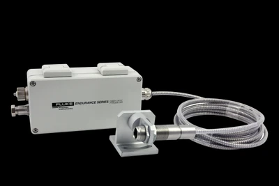
The Endurance Fiber-Optic pyrometer separates the optics from the electronics: a small optical head on a flexible, armored fiber cable looks into the hot, tight, or electrically-noisy spot, while the IP65 electronics box sits somewhere cooler and reachable. Like the integrated line it ships in both principles — ratio (EF1R, EF2R) for measurement through attenuation, and single-color (EF1M, EF2M) — over 250 to 3200 °C. The head tolerates 200 °C (315 °C high-temp) so only the small front end sees the heat. Choose fiber-optic when an integrated sensor cannot physically go where the measurement is — behind a furnace wall, between rolls, or inside an induction coil.
Key Features & Benefits
- Puts the optics where the sensor cannot go — a small fiber head on a flexible armored cable reaches behind a wall, between rolls, or inside a coil, while the electronics stay in an accessible spot. The measurement point and the electronics no longer have to share a location.
- Only the small head sees the heat — the head and cable are rated far hotter than the electronics box, so a high-ambient or high-EMI location stops being a reason to cool, relocate, or give up the measurement. The heat-exposed part is the cheap, rugged part.
- Ratio or single-color, same as the integrated line — EF-R models read through attenuation by ratio; EF-M models give single-color accuracy — the fiber format does not cost you the choice of principle. Pick the principle the target needs, in a fiber package.
- Immune to the electrical noise around induction heating — the optical path carries no signal current, so the strong fields around induction and arc processes do not couple into the measurement the way they can on a wired head. Fiber sidesteps the EMI that plagues metal-melting installs.
- Full fieldbus set on the remote electronics — Ethernet/PoE, Profinet, EtherNet/IP, 4–20 mA, and RS485 all terminate at the accessible electronics box, not at the buried head. You wire and service the box, not the hot spot.
Specifications
- Measurement principle
- Both principles, with the optics separated from the electronics by a fiber-optic cable. The R models (EF1R, EF2R) are 2-color (ratio) — ratio measurement reads through attenuation, which matters when the fiber head looks into a hot, tight, or partly obscured spot. The M models (EF1M, EF2M) are single-color. The small optical head and flexible fiber go where an integrated sensor cannot; the electronics box sits in a cooler, accessible location.
- Models & temperature range
- Ratio (2-color): EF1RL 500–1100 °C, EF1RM 700–1500 °C, EF1RH 1000–3200 °C, EF2RL 275–1000 °C, EF2RH 350–1300 °C. Single-color: EF1ML 475–900 °C, EF1MM 800–1900 °C, EF1MH 1200–3000 °C, EF2ML 250–800 °C, EF2MH 400–1700 °C. Family envelope 250 to 3200 °C (482 to 5792 °F).
- Spectral response (wavelength)
- 1.0 µm nominal (EF1R one/two-color, EF1M single-color) · 1.6 µm (EF2R one/two-color, EF2M single-color). Both are short-wavelength bands for hot metals, molten metal, and induction work — the temperatures where a fiber head most often earns its place.
- Optical resolution (D:S)
- To 100:1, set by the fixed-focus lens (F0 20:1, F1 40:1 or 65:1, F2 100:1) and by model: EF?L 20:1, EF1RM / EF2RH 40:1, EF1RH 65:1, EF1MM / EF1MH 100:1.
- Focus & lens options
- Fixed-focus lenses (all four lens groups are fixed focus): F0 20:1 (5 mm @ 100 mm), F1 40:1 (2.5 mm @ 100 mm), F1 65:1 (1.5 mm @ 100 mm), F2 100:1 (1 mm @ 100 mm). Choose the lens to the mounting distance.
- Smallest measurement spot
- Smallest spots: 1 mm @ 100 mm (100:1 lens), 2.5 mm @ 100 mm (40:1), 5 mm @ 100 mm (20:1); at 5000 mm the 100:1 lens reads a 50 mm spot.
- Accuracy
- ±(0.3% Tmeas + 2 °C) with no attenuation, ratio and single-color alike.
- Repeatability
- ±1 °C.
- Response time
- 10 ms (95%) on EF1R, EF1M, and EF2M; 20 ms on EF2R.
- Temperature resolution
- Digital output 0.1 °C; current output <0.03 °C / 16-bit.
- Emissivity & e-slope
- Emissivity 0.100 to 1.150; e-slope (ratio models) 0.850 to 1.150.
- Signal processing
- Peak hold, valley hold, and averaging on board, with a fail-safe alarm.
- Sighting / aiming
- Laser aiming optional — a battery aiming-light for the fiber-optic front end ships standard with all units (best suited to the “L” range models).
- Outputs & communications
- Ethernet/LAN with PoE (ASCII, webserver), Profinet and EtherNet/IP options, 0/4–20 mA (max load 500 Ω), RS485 (2/4-wire half-duplex; 4-wire only with the inside-connector electronics box), networkable relay (48 V, 300 mA).
- Inputs
- Contact input (peak/valley reset, laser) and analog input 0/4–20 mA (emissivity, e-slope, background temperature).
- Power supply
- 20 to 48 VDC, 500 mA, or Power-over-Ethernet (PoE).
- Ambient temperature & cooling
- Electronics housing 0 to 60 °C; to 150 °C with water cooling (2 L/min @ 16 °C) or the cooling plate. The fiber head tolerates 200 °C (315 °C high-temp option), so the heat-exposed part is the small head, not the electronics. Storage −20 to 70 °C.
- Enclosure & environmental rating
- Rugged electronics-box housing, IP65 (NEMA-4) rated; 10–95% RH non-condensing. Electronics box 0.71 kg, optical head 0.10 kg.
- Shock & vibration
- Electronics housing: shock to IEC 68-2-27, vibration to IEC 68-2-6.
- Fiber-optic head & cable
- Small optical head (0.10 kg) with a 3/4″–16 UNF 2A thread, connected by fiber cable to the electronics box. Fiber cable / optical head rated 0 to 200 °C standard, 0 to 315 °C high-temperature option; cable protected by stainless-steel armor with a PTFE coating, rubber boot, and IP65 / NEMA-4 (standard cable). Minimum bend radius 19 mm.
- Software
- Endurance software for remote configuration, monitoring, and field calibration.
- Warranty
- 4-year warranty.
- Mounting & accessories
- Adjustable mounting bracket, air-purge collar with a 150 mm stainless sight tube, rooftop mount/purge fittings, sapphire protective windows, and the FOXH3 / FOXH6 high-temperature air-knife housings (ambient ≤450 °C) for extreme environments.
Common Applications
- Induction-hardening and induction-melting temperature, inside the coil’s field
- Vacuum and controlled-atmosphere furnaces — head in, electronics out
- Tight inter-roll and inter-stand gaps on a rolling mill where a full sensor will not fit
- High-ambient locations near a furnace wall, with the electronics relocated to a cool spot
- Molten-metal and forging temperature in electrically noisy bays
- Glass-forming and high-temperature metal targets behind a protective wall or window
Design & Selection Considerations
- Use fiber for access and ambient, not for a longer cable run — the fiber format earns its cost where an integrated sensor physically cannot mount — a hot, tight, or high-EMI spot — with the electronics relocated to a reachable, cooler place. If an integrated sensor fits, it is simpler and cheaper. Pick fiber for the access problem it solves, not by default.
- Respect the fiber bend radius and the cable temperature rating — the cable has a minimum bend radius and a 200 °C standard rating (315 °C high-temp option); a kinked or over-hot cable degrades the signal. Route it with gentle bends and keep it inside its rating, using the armored protection where it is exposed. The cable is the part that fails if it is abused.
- Choose the fixed-focus lens to the actual mounting distance — fiber lenses are fixed focus (20:1 to 100:1), so the lens is chosen for the standoff up front — there is no field refocus. Confirm the working distance and the smallest target before you order the lens. Get the standoff right at quote time; you cannot dial it in later.
- Ratio still goes to a ratio successor — an EF-R is a 2-color instrument; if you are replacing a legacy ratio fiber sensor, stay on the ratio path (EF1R/EF2R) rather than dropping to single-color — the measurement principle has to be preserved. 2-color in, 2-color out.
- Plan air purge and a protective window for the head — the small head looks straight into the process; an air-purge collar and a sapphire window (or the FOXH high-temperature housing) keep the optic clean and the head alive in an extreme environment. Protect the head the way you would protect any optic facing a furnace.
To spec the right Endurance fiber-optic pyrometer:
Use the input form to tell us about the measurement and the configuration follows from it: target material and its emissivity (and surface finish / oxidation); the process temperature range; the wavelength / spectral fit for the material; the working distance and smallest target so we set the optics and D:S (spot size at distance); whether the path argues for 2-color (ratio) or single-color; the mounting and ambient (and any cooling or purge needed); and the output / comms your control system expects (4–20 mA, RS485, Profinet, EtherNet/IP, relay).
IR Pyrometer Application Sheet ›Talk to an engineer directly — Scott Prater, Principal · 917-580-0878 · scott@pratertechnical.com
Specifications compiled by Prater Technical Partners from Fluke Process Instruments product datasheets.