About this category
Fluke Process Instruments (FPI) — industrial non-contact IR temperature measurement for the surfaces a thermocouple can’t touch: moving webs and rotating kiln shells, molten metal and glass, energized equipment, and targets too hot, too fast, or too far to reach. Whether you need a single monitoring/control point, a temperature profile across a moving product, or a full thermal image of a process, there’s an instrument matched to it — Endurance single-color and 2-color ratio pyrometers, Thermalert 4.0 spot sensors, MP and MP150 line scanners with CS400 kiln-shell monitoring, and ThermoView imagers, alongside the still Raytek-branded series, from the compact Mi3, CI, CM, and GP sensors to the 3iPlus portable short-wave handheld. Discontinued Ircon and legacy Raytek instruments map to current FPI replacement series — with the 2-color (ratio) measurement principle preserved through every migration. Prater Technical works with you to spec Fluke Process Instruments by material, process temperature range, spectral band, and optics.
Fluke Process Instruments SeriesShop Raytek lines →
Click any Series box for details →
 FPI · Raytek · Ircon — non-contact IR
FPI secondary brands

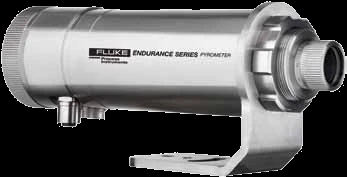
Endurance Integrated 2‑Color & 1‑Color
E1R·E2R ratio + E1M·E2M·E3M spot — 50 to 3200 °C
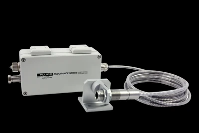
Endurance Fiber‑Optic Pyrometers
EF1R·EF2R ratio + EF1M·EF2M — High‑ambient optics
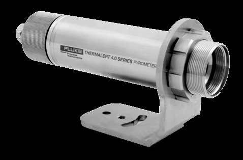
Thermalert 4.0 Single‑Color Spot
LT·G5·P‑series·1M·2M·3M + flame — −40 to 2300 °C
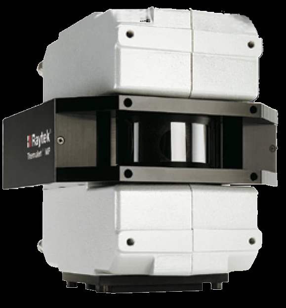
FPI · Ircon · Raytek Line Scanners
MP shortwave & MP150 + CS400 kiln‑shell — MP‑SYS apps
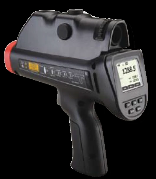
Raynger 3i Plus Portable Handheld
1M & 2M — 400 to 3000 °C, D:S 250:1, dual laser
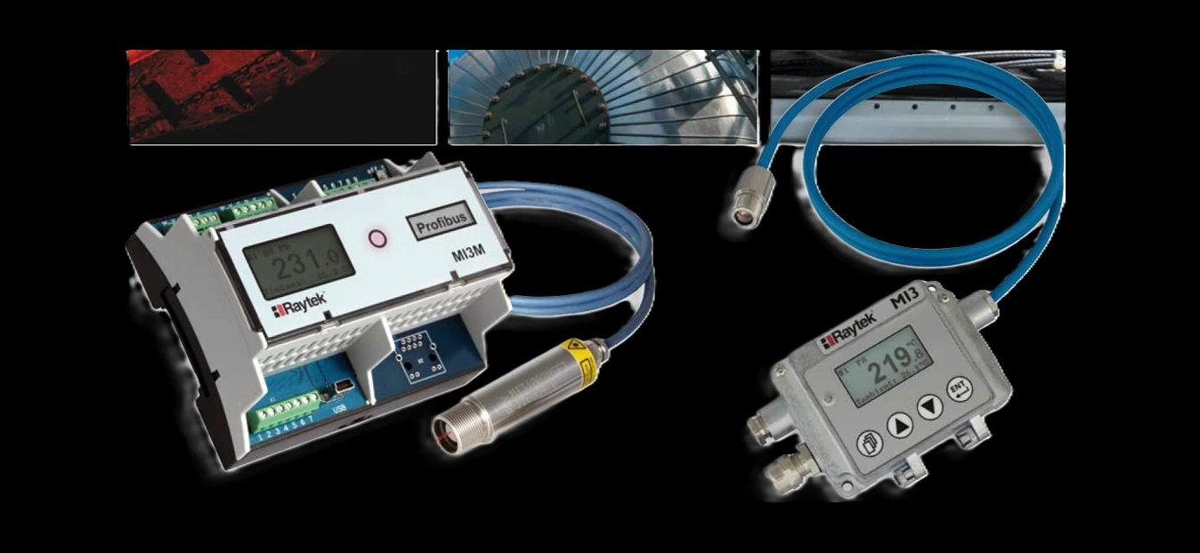
Raytek Mi3 Compact Modular Sensors
Comm box · plug‑and‑play multi‑head — Nationwide stock
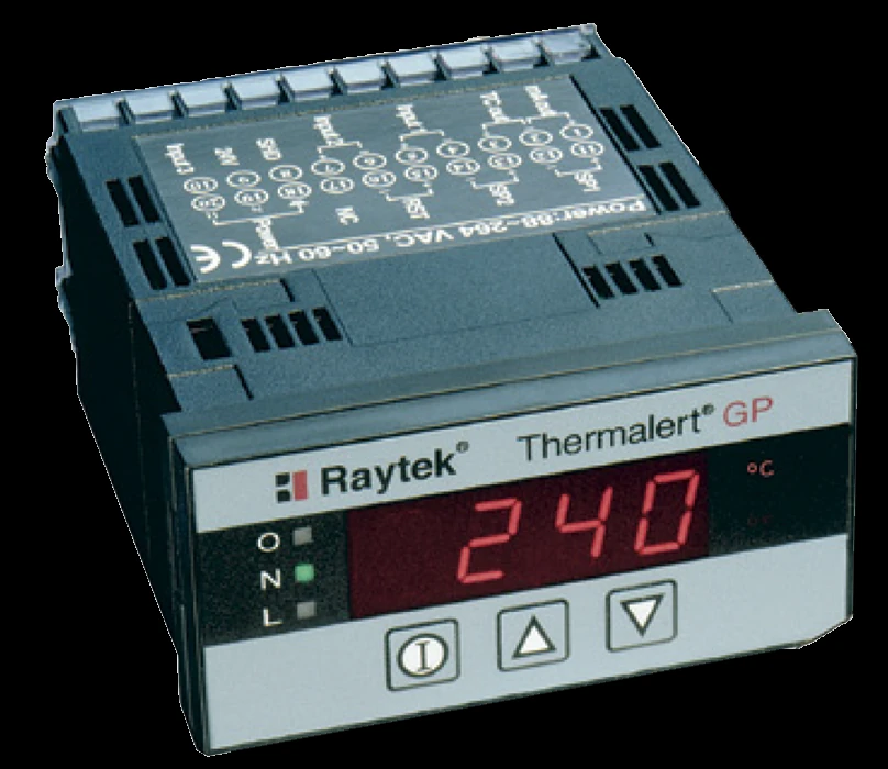
GP Monitor Display
1/8 DIN local display + GPR/GPS head; also CI · TX · Mi
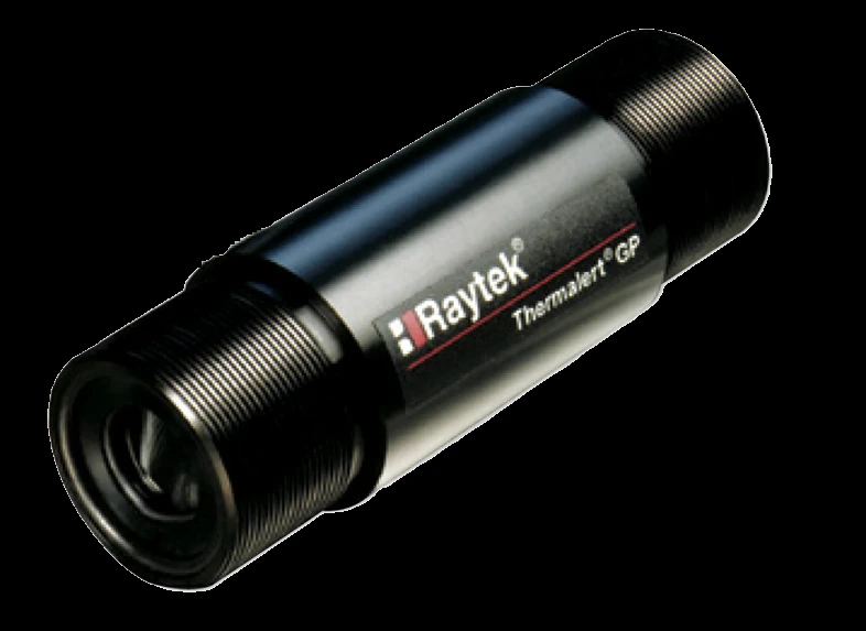
GP Series Pyrometers
GPR/GPS two‑piece — 8–14 µm, −18 to 538 °C
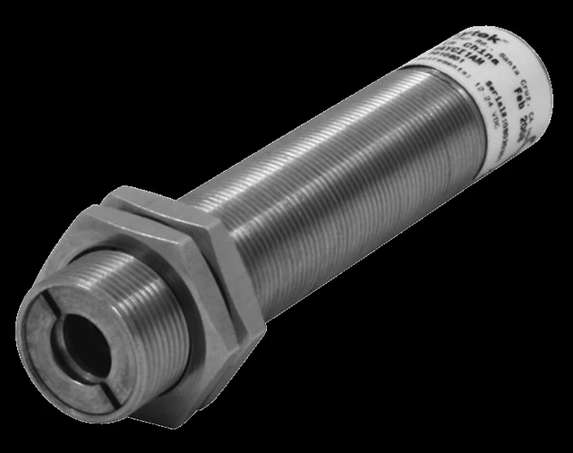
CM / CI Embedded OEM Sensors
Stainless threaded — J/K TC or 0–5 V, to 500 °C
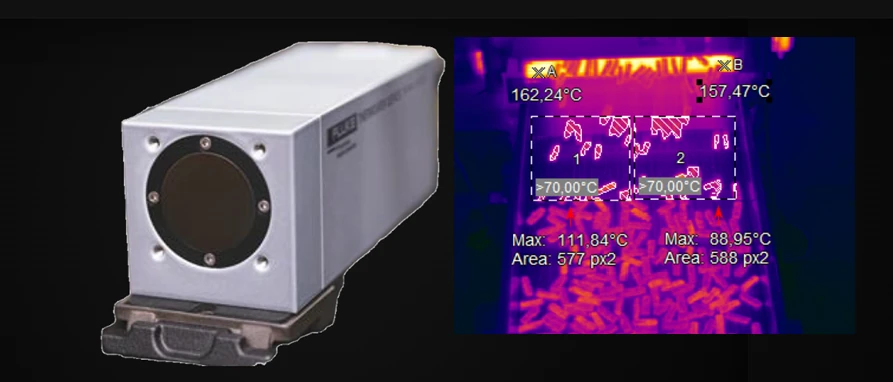
ThermoView TV30 Fixed Thermal Imagers
TV33 320×240 · TV36 640×480 — −10 to 1300 °C
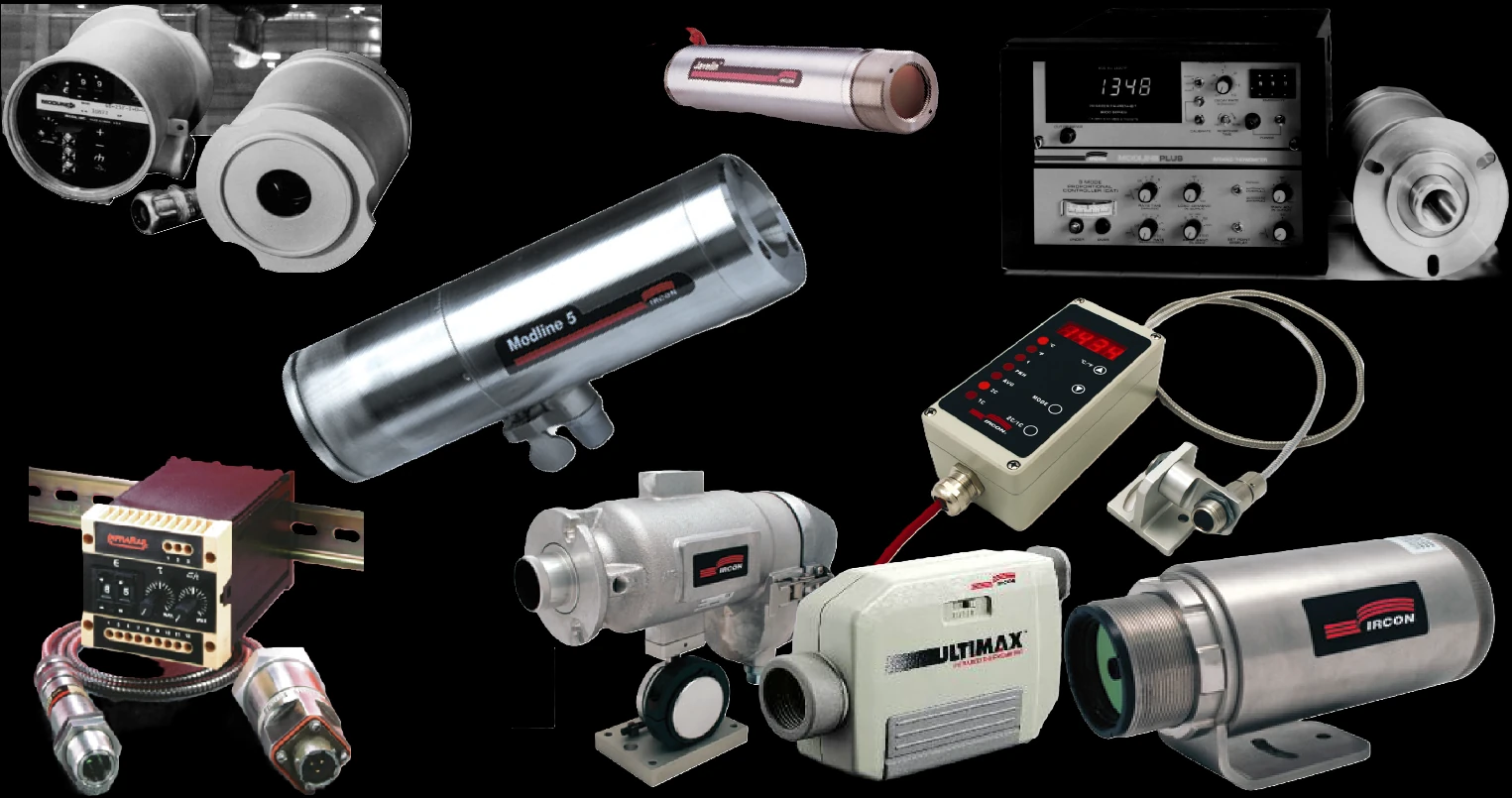
Ircon Legacy Migration Reference
Modline·Maxline·ScanIR → Endurance/Thermalert
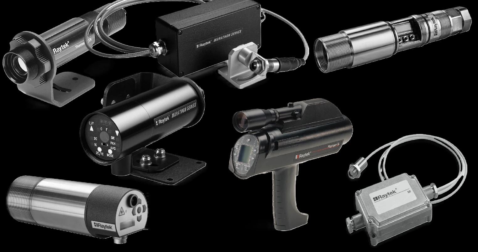
Raytek Legacy Migration Reference
Marathon MM/MR · XR · ThermoView → current lines
Industries Served
Metals & Steel
Glass
Plastics & Rubber
Cement & Lime
Pulp & Paper
Semiconductor
Power Generation
Foundry & Forging
FAQ: IR pyrometers & thermal imagers
How do IR sensors work?
Every object above absolute zero radiates energy, and a measurable share of it falls in the infrared band of the electromagnetic spectrum. An IR sensor — a/k/a a pyrometer, infrared thermometer, or thermal imager (across a field of view) — collects that radiation through a lens, optically filters it to a specific wavelength range (its spectral response), and focuses it on a sensing element. The detector converts the radiated energy into an electrical signal proportional to the target's temperature, which is then scaled and sent to a local display or a control system. Because it reads from a distance with nothing touching the target, an IR sensor measures surfaces a thermocouple or RTD cannot — moving webs and rolls, energized equipment, and hot or hard-to-reach objects. Two setup decisions govern accuracy: choosing the right spectral response for the material, and entering the correct emissivity. Emissivity is the fraction of energy a surface radiates compared with a perfect blackbody at the same temperature; on an opaque surface the remainder is ambient energy reflected onto the surface, and for some materials energy transmitted from behind. So emissivity plus reflectivity plus transmission (if any) equals one — and it is further affected by surface finish, oxidation, and wavelength choice, which is why it has to be specified and set deliberately, not left at a default.
Which spectral response (a/k/a wavelength) should I use?
Each spectral range reads surface temperature based on the material — match the wavelength to the target. 8 to 14 µm — plastics (thick/opaque), paper, painted and organic surfaces; general-purpose for low to medium temperatures. 7.9 µm — thin polyester films (PET, PETG), polyurethane, and other plastic films that are transparent at 8–14 µm but absorb strongly here. 5 µm — glass surface temperature; glass is opaque at 5 µm, so the reading represents the surface rather than energy transmitted from behind it (flat glass, container glass). 3.43 µm — thin polyethylene and polypropylene films; polyolefins that transmit at longer wavelengths but absorb at 3.43 µm. 1 to 2 µm (typically 1.0, 1.6, and 2.2 µm) — high-temperature metals, molten metals, induction-heated parts, and semiconductors; short wavelengths reduce the temperature error caused by emissivity uncertainty and work well at high target temperatures. Picking the wrong wavelength is the most common cause of a reading that looks wrong no matter how the emissivity is set — for example, sighting a thin film with an 8–14 µm sensor and unknowingly reading the roll behind it.
How do you calibrate an IR sensor?
There are two distinct exercises, and people use "calibrate" for both. The first is dialing in emissivity to a known material temperature: if a surface thermocouple/RTD reading is possible, adjust the pyrometer's emissivity setting up or down until the IR reading matches. For a reference temperature, three field methods work — (A) a thermocouple or RTD touching the material at process temperature; (B) coat a patch of the target with a material of known high emissivity, such as flat-black high-temperature paint, read the patch, then adjust emissivity on the bare surface to match; (C) apply Kapton tape, which has a known emissivity of about 0.95 in the 8–14 µm range, to a section of web material at process temperature, preset the pyrometer to 0.95, read the tape, then adjust the emissivity setting while looking at the bare material after the tape section has passed. The second use of "calibrate" is verification against a blackbody calibration source — a lab device with a known, traceable emissivity of 1.0; the blackbody is what the emissivity scale is referenced to. NIST- and DAkkS-traceable calibration certificates are available as a line item on any Fluke Process Instruments and Raytek sensor and should be renewed on the interval your quality system requires.
How do you mount an IR sensor?
Typical mounts include single-axis "L" brackets, two-axis "double-L" brackets, and swivel or flange-mount accessories. Beyond the hardware, three things matter: for single-color pyrometers, aim the sensor so the target fully fills the measured spot at the working distance (see distance-to-spot, below); keep the line of sight clear of steam, dust, and obstructions (a 2-color instrument can tolerate these); and where the optics face a dirty or hot process, add an air purge to keep the lens clean and a cooling accessory to keep the housing in range. Avoid sighting through a window unless the window material is transparent at the sensor's wavelength, and set the window transmissivity value into the pyrometer interface.
Can IR sensors withstand high heat?
The sensor's electronics must stay within their rated ambient temperature. That limit varies by series and detector type, but as a guide most fixed sensors are rated roughly 0 to 65 °C uncooled, with the longwave Thermalert 4.0 spot sensors among the highest in the category at −20 to +85 °C uncooled. Past that, cooling accessories extend the envelope: with an air-cooling jacket and clean instrument air, often to about 120 °C ambient; with a water-cooled housing, often to about 175 °C ambient; with a water-cooled housing plus an air-purged over-jacket (for example the ThermoJacket), often to about 315 °C ambient. The target temperature the sensor reads is a separate spec — pyrometers measure up to 3000 °C+. The ambient ratings above are about protecting the instrument itself.
What drives the cost of an IR pyrometer?
Cost generally scales with the optics (the distance-to-spot ratio), the feature set, and the accuracy rating. A short-wavelength, high-D:S sensor with a ratio (2-color) detector and a high accuracy class costs more than a general-purpose 8–14 µm single-color sensor with modest optics. The rep-firm lines are quote-only; tell us the application and the configuration follows from it.
How rugged are IR sensors, and how long do they last?
If kept within their rated ambient temperature and not physically damaged, IR sensors often last many years — in some cases decades. They have no moving parts in the measurement path; the practical life-limiters are heat soak on the electronics, optics damage or contamination, and cable wear, all of which good mounting and cooling prevent. Fixed industrial pyrometers are built for the plant floor: sensing heads are housed in stainless-steel bodies sealed to IP65 / NEMA-4 against dust and washdown; the ThermoView fixed thermal imagers carry an IP67 rating and are qualified to IEC shock (50 g) and vibration (3 g) standards for harsh installs; portable instruments such as the Raynger 3i Plus are drop-rated (about 1 m / 3 ft). The vulnerable part is the optics, not the housing — an air purge that keeps the lens clean and a cooling accessory that holds the body in its ambient range are what let these instruments survive years in rolling mills, glass plants, and kilns, short of physical damage.
Who invented the IR temperature sensor?
Infrared radiation itself was discovered by astronomer William Herschel in 1800, when he measured a temperature rise just beyond the red end of a prism's spectrum. Practical non-contact thermometry followed a century later: the disappearing-filament optical pyrometer, in which an operator matched the brightness of a hot target against a calibrated lamp filament, was developed around 1901 by Holborn and Kurlbaum. Fully electronic photoelectric pyrometers — the direct ancestors of today's instruments — came into industrial use through the mid-20th century, and the uncooled focal-plane detector made compact fixed thermal imagers practical from the 1990s onward.
Two-color (ratio) or single-color — which should I specify?
Specify a two-color (ratio) pyrometer when the target may be partially obscured (dust, steam, smoke), when the optics will get dirty in service, when the target underfills the field of view, or when emissivity drifts during the process. A ratio instrument measures at two wavelengths at once and cancels common-mode attenuation, so it reads accurately through those conditions. Specify single-color for clean, well-defined targets that fully fill the field of view, where emissivity is stable and known — single-color delivers higher absolute accuracy and faster response on those targets. The Endurance line, E1R/E2R (integrated) and EF1R/EF2R (fiber-optic), covers the ratio cases; E1M/E2M/E3M, the Thermalert 4.0, Raytek Mi3, GP, CI/CM, and the 3iPlus portable cover single-color.
What is the difference between a spot pyrometer, a line scanner, and a thermal imager?
All three measure radiated temperature; they differ in how much of the scene they cover. A spot pyrometer reads one point — fastest response, highest absolute accuracy, simplest to install; right for a single control point such as an induction-heated billet or an extruder melt. A line scanner sweeps a single line across the process at 150–300 Hz and reports up to 1,024 points along it — right for moving webs and surfaces where you need a temperature profile across the width, such as rolling mills, glass lines, paper drying, and thermoforming. A thermal imager captures a full two-dimensional image (320×240 or 640×480 pixels on the ThermoView line) — right for process and R&D monitoring, and for safety of areas or assets where hot spots can appear, such as electrical gear or furnace exteriors. As a rule: one control point → spot; a profile across a moving product → line scanner; a thermal profile for process, R&D, or area/asset safety monitoring → imager.
Can an IR sensor measure through a window, a sight tube, or a flame?
Through a window — yes, but only if the window material is transparent at the sensor's wavelength, and the window transmission value is dialed into the pyrometer settings. Ordinary glass blocks longwave IR, so an 8–14 µm sensor cannot read through it; shortwave (1–2 µm) instruments can use glass or quartz windows, and purpose-made windows exist for other bands. A sight tube is the standard way to give a sensor a clean, defined line of sight into a furnace or a dusty enclosure. Measuring a flame, or measuring a target through a flame, is a specialized case: dedicated flame-measurement sensors (CO₂, CO, NOX bands) read combustion, while reading a target behind a flame calls for a wavelength where the flame is transparent. For flare-stack monitoring, the pyrometer watches and alarms on cessation of the flame. Tell us the obstruction and we will specify the wavelength around it.
My IR reading does not match my contact thermometer — why?
This is the most common IR support call, and it is often not a broken sensor. Work through, in order: (1) Emissivity — a wrong value is the usual culprit; a bare metal surface set to a default 0.95 will read far low. (2) Reflected or transmitted ambient energy — a low-emissivity target near a hotter surface reflects that heat into the sensor and reads high; for visually transparent materials, heat sources from behind can transmit through and skew the reading; proper emissivity adjustments and, in some cases, background-temperature compensation correct it. (3) Cone of view from the pyrometer face to the material — if the target does not fully fill the measured spot (for single-color pyrometers), the sensor averages in whatever is behind or around it. (4) Wavelength mismatch — sighting a thin film or glass with the wrong band reads the wrong layer entirely. (5) Dirty optics or an obstructed path — steam, dust, or a filmed lens attenuate the signal (single-color, or in extreme conditions two-color). And remember the reference contact sensor can be wrong too — poor surface contact reads low. A ratio pyrometer sidesteps several of these failure modes at once.
Can I replace a legacy or discontinued pyrometer?
Yes — discontinued Ircon Modline, Maxline, and ScanIR units, and legacy Raytek sensors (Marathon MM/MR, XR, legacy Thermalert), all have defined migration paths to the current Endurance and Thermalert 4.0 lines. Prater recommends the correct successor based on the legacy nameplate and/or part number and process data, and supports existing installations still in service. The migration always preserves the measurement principle: 2-color (ratio) instruments migrate to Endurance E1R/E2R (integrated) or EF1R/EF2R (fiber-optic), never to a single-color successor; single-color instruments follow their own path.
How do I pick the right optics — what is distance-to-spot ratio?
Distance-to-spot ratio (D:S) tells you how large a spot the sensor measures at a given working distance. A 100:1 sensor reads a 10 mm spot at 1 m; a 10:1 sensor reads a 100 mm spot at the same distance. The rule is simple: the measured spot must be fully filled by the target (for single-color use) — if the spot is larger than the target, the reading is skewed by whatever surrounds it, since cooler or hotter surrounding items factor into the reading. Choose the D:S from your two fixed facts: how far the sensor must mount from the target, and how small the target is. Small targets or long standoffs need a high ratio; close, large targets can use a modest one. The IR line spans roughly 4:1 close-focus up to 250:1, with line scanners detecting hot spots at 600:1 — tighter optics generally correlate to cost, which is why D:S is the first thing to nail down. A 2-color (ratio) pyrometer can lose as much as 95% of combined energy from an underfilled or obstructed spot, retaining as little as 5% in some cases, and still get a good measurement.
Which IR lines are stocked, and how fast can I get one?
Most Fluke Process Instruments and Raytek lines — Endurance, Thermalert 4.0, GP, the ThermoView imagers, and the MP line scanners — are rep-firm, quote-only, and built to the configuration. The exception is the Raytek compact sensor families (Mi3, CI/CM, 3iPlus), sold through Prater Technical Partners under authorized distribution: select SKUs ship from Brooklyn stock, while others are special order — contact us for lead time. Tell us the p/n or application and we will confirm whether a stocked SKU fits before you commit.
Migration question or application help? Talk to Scott — send directly to Scott Prater at scott@pratertechnical.com, or call him directly at 917-580-0878 during business hours.
Territory Coverage
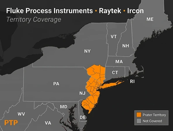
New Jersey: Entire state
New York: NYC, Long Island, Hudson Valley & Catskills
Nationwide: Raytek Mi3 / CI / CM / 3iplus — authorized distribution
New York: NYC, Long Island, Hudson Valley & Catskills
Nationwide: Raytek Mi3 / CI / CM / 3iplus — authorized distribution
Territory shown applies to Fluke Process Instruments and Raytek rep-firm lines. Raytek Mi3, CI, CM, and 3iplus series are authorized for sale nationwide. Other manufacturer lines have their own coverage — see each brand’s page.
Specifications compiled by Prater Technical Partners from Fluke Process Instruments product datasheets.