Product Overview
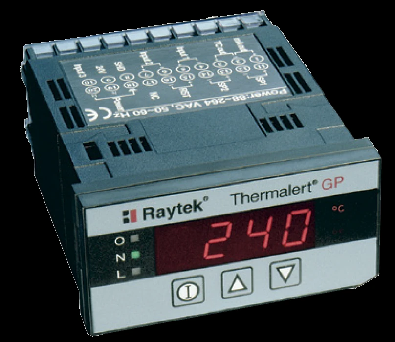
The GP Monitor (Raytek GPC / GPCM) is a compact 1/8 DIN panel-meter display and alarm interface for a process instrument — not a sensor. It accepts the signal from an infrared sensor (or any 0–5 V, 4–20 mA, or thermocouple source), shows it on a large 4-digit LED, processes it with Peak/Valley hold and averaging, and drives two setpoint alarms — 5 V logic on the RAYGPC or 3 A mechanical relays on the RAYGPCM. A 24 VDC excitation output loop-powers the attached sensor, and every function is set from the front panel. It is the local face and control point for a fixed sensor that has no display of its own — pair it with a GP Series (GPR / GPS) sensing head, or use it to read a Compact-Series or Endurance sensor you already run.
Key Features & Benefits
- Turns a bare sensor signal into a panel reading and an alarm — it takes the 4–20 mA, 0–5 V, or thermocouple output of an IR sensor (or any compatible source), shows it on a 4-digit LED, and trips a relay or alarm at a setpoint — the local face and control point for a sensor that has none of its own. Where you want the operator to see the temperature and the process to act on it, at the panel.
- Accepts almost any sensor you put in front of it — one universal input handles 0–5 V, 4–20 mA, and seven thermocouple types, and it loop-powers the sensor from its own 24 VDC excitation. One display SKU covers a mixed fleet of sensors instead of a different meter for each.
- Signal processing usually found on far larger systems — Peak and Valley hold, a 60-second averaging filter, and an adjustable offset clean up a noisy or intermittent target right at the meter, with no PC. Catch the peak on a moving part or smooth a flickering reading without a control-system change.
- Configured entirely from the front panel — every function — input type, setpoints, deadbands, °C/°F, hold, averaging — is set from the front, with no internal jumpers to pull the meter for. Commission and re-range it in place.
Specifications
- Instrument type
- Local display / panel meter — a compact 1/8 DIN digital panel meter that reads, shows, and processes the signal from a process instrument. It is not a sensor: it has no optics and makes no temperature measurement of its own — it displays and acts on the signal an attached sensor provides.
- Models & spectral variants
- RAYGPC — panel meter with 5 VDC alarm outputs; RAYGPCM — with 3 A mechanical relays and fully isolated I/O.
- Accuracy
- Input resolution / accuracy: 0–5 V to ±2 mV; 4–20 mA to ±0.02 mA; J/K/E/N/T thermocouple ±0.05% or ±2°C; R/S thermocouple ±0.5% or ±3°C (whichever is greater).
- Repeatability
- System repeatability ±0.5% of measured value.
- Response time
- 500 ms (95%); 5-second warm-up.
- Signal processing
- Peak Hold, Valley Hold (to 998 s; 999 = infinite hold with external reset) and a variable averaging filter (to 60 s), with a user-adjustable offset.
- Outputs
- A user-defined 4–20 mA current or thermocouple (J/K/E/N/R/S/T) re-transmit output, plus two adjustable setpoints with deadbands driving +5 V alarm outputs or optional 3 A mechanical relays (GPCM). A 24 VDC / 50 mA excitation output can loop-power an external sensor.
- Inputs
- User-configurable for any 0–5 V or 4–20 mA sensor, or a type J, K, E, N, R, S, or T thermocouple. Works with many Raytek non-contact infrared sensors (e.g. the GP / Compact Series heads) and with the Endurance line; an external reset input clears the Peak/Valley hold.
- Display
- Large 4-digit, 7-segment LED display, °C / °F selectable. All functions are configured from the front panel — no internal jumpers.
- Ambient operating temperature
- 0°C to 50°C (32°F to 120°F); storage −30°C to 65°C; humidity 10–95% non-condensing.
- Enclosure / rating
- Front panel IP54 (IEC 529) / NEMA-12; panel cut-out 92×44 mm (1.75×3.63″).
- Power
- Universal 110/220 VAC ±20%, 50–60 Hz; provides a 24 VDC / 50 mA sensor excitation. 320 g; 1/8 DIN × 120 mm deep.
- Mounting & fittings
- Panel-mount; mounting hardware included. Optional sub-panel mounting bracket (XXXGPACFB) and external 10 A AC isolated solid-state relays (XXXGPSSRAC) for the alarm outputs.
- Options & accessories
- 3 A mechanical relay version (GPCM, specified at order), external solid-state relays, and the sub-panel mounting bracket.
- Lead time & warranty
- Built to the RAYGPC / RAYGPCM variant and ordered options; quoted per application.
Common Applications
- A local temperature readout and alarm for a fixed IR sensor at a machine or line
- Panel-mounted display for a Raytek Compact-Series (GP / CI / TX / Mi) or Endurance sensor
- Setpoint / deadband alarm control driving a contactor or annunciator from a sensor signal
- Peak-hold capture of the hottest point on a moving or intermittent target
- Re-transmitting a sensor reading as a scaled 4–20 mA or thermocouple signal to a PLC
Design & Selection Considerations
- This is the display, not the sensor — the GP Series is the sensing head — the GP Monitor reads and acts on a signal; it does not measure temperature itself. The matching sensing head is the GP Series (GPR / GPS), which is a separate page. Order the monitor with a head, or to read an Endurance / Compact-Series sensor you already have. Decide sensor and display together so the input type and excitation match.
- Match the input type and the alarm output to your loop — the meter is configured for the sensor’s signal (0–5 V, 4–20 mA, or a specific thermocouple) and for how the alarm has to act — a 5 V logic output (RAYGPC) or an isolated 3 A mechanical relay (RAYGPCM). Pick the variant for the contact your control panel expects; the relay version must be specified at order.
- Mount it where the operator and the wiring are, in its ambient range — a panel meter belongs in a control panel or enclosure within 0–50°C and away from the process heat the sensor lives in; its IP54 front suits a panel face, not a washdown wall. Keep the meter cool and dry even when the sensor it reads is in the fire.
- Use the on-board processing before reaching for a PLC — Peak/Valley hold and averaging often solve the intermittent-target or noisy-signal problem at the meter, saving a control-system change. Try the built-in signal processing first; it is already paid for.
To spec the right GP Monitor and sensor:
Use the input form to send the target material and its emissivity (known or to be established), the lowest and highest target temperatures, the wavelength / spectral fit if you know it, the working distance and the size of the target (or smallest hot spot) you need to resolve, the ambient temperature and any line-of-sight obstruction at the mount, and the output or protocol your control system expects (4–20 mA, relay/alarm, Ethernet, fieldbus, or OPC) — and we’ll spec the right FPI / Raytek instrument and optics for your application.
IR Pyrometer Application Sheet ›Talk to an engineer directly — Scott Prater, Principal · 917-580-0878 · scott@pratertechnical.com
Specifications compiled by Prater Technical Partners from Fluke Process Instruments product datasheets.