Product Overview
The ThermoView® TV40 is a fixed, stand-alone 2D thermal imager — a rugged focal-plane camera that captures a full two-dimensional thermal image of a scene with multiple on-board areas of interest, from −10°C to 1200°C in the general-purpose 8–14 µm band. It is the instrument for the question "where across this asset is it getting hot": electrical gear, furnace and kiln exteriors, press hardening, waste incinerators, and process or R&D monitoring where a single point will not do. Two detectors — TV43 at 320×240 and TV46 at 640×480 — pair the thermal imager with an integrated 640×480 visible-light camera, so IR-Fusion® blended sighting puts the hot spot in its visible context, and field-interchangeable lenses frame the scene. It streams GigE Vision at up to 60 frames/s over a single Power-over-Ethernet cable, with an embedded web server and ThermoView software for factory-automation monitoring, alarming, and archived traceability, in a compact IP67 body built to stay sealed where commercial cameras cannot.
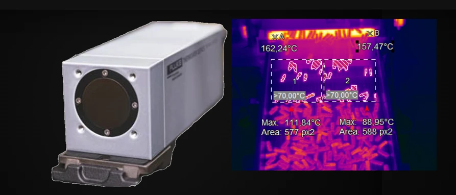
Key Features & Benefits
- Sees the whole scene as a live thermal picture — a focal-plane array renders a full 2D thermal image with multiple areas of interest, so a hot spot can appear anywhere in the field of view and still be caught and alarmed. The right tool when the question is "where on this asset is it getting hot," not "what is the temperature of one point."
- IR-Fusion blends thermal and visible for sure sighting — an integrated 640×480 visible-light camera overlays the thermal image, so you can verify the imager is aimed at the right asset — remotely, over the network — and read a hot spot against the visible scene around it. You see what is hot and exactly where it sits on the machine.
- GigE Vision and PoE drop it straight into the plant network — a 60-frame-per-second GigE Vision stream over a single Power-over-Ethernet cable, plus Ethernet/IP and discrete I/O to a PLC, integrate the imager into a factory-automation system without a separate power run. One cable for power and high-speed data; native fit for plant controls.
- ThermoView software for monitoring, alarming, and traceability — beyond live viewing, ThermoView runs continuous or triggered inspection, alarms on temperature events through I/O, and archives images and AOI trend data for product-quality traceability; ThermoView Lite and the embedded web server cover start-up and basic viewing. Process control and a record of it, not just a picture.
- Built to stay sealed in rugged service — an IP67 (NEMA 4) housing with industrial sealed connectors, qualified to 50 g shock and 3 g vibration, with an air-purge collar and a water-cooled enclosure on the options list, keeps it imaging in conditions that retire a commercial camera. An industrial fixture, not a handheld pressed into a permanent install.
Specifications
- Instrument type
- Fixed (stand-alone) 2D thermal imager — a focal-plane camera that captures a full two-dimensional thermal image of a scene, with multiple on-board areas of interest (AOIs) and an integrated visible-light camera for blended sighting. Distinct from a spot pyrometer (one point) and a line scanner (a profile across a moving product).
- Measurement principle
- Single-color (8–14 µm broadband) uncooled focal-plane-array radiometry across every pixel of the image.
- Temperature range
- −10°C to 1200°C (14°F to 2192°F), with selectable subranges (−10 to 80°C and −10 to 250°C) for finer resolution on low-temperature scenes.
- Spectral response / wavelength
- 8–14 µm — the general-purpose longwave band for low-to-medium-temperature opaque surfaces (electrical assets, furnace exteriors, painted and organic surfaces).
- Models & spectral variants
- TV43 (320×240 detector) and TV46 (640×480 detector) — same envelope, different infrared resolution; both pair the thermal imager with a 640×480 visible-light camera.
- Imaging resolution
- TV43: 320×240 (76,800 pixels) · TV46: 640×480 (307,200 pixels) — the choice sets how fine a hot spot the image resolves at a given distance.
- Field of view
- 34°×25.5° standard (on-board lens). Field-interchangeable add-on lenses: 0.75× wide-angle 45°×34°, 2× 17°×12.7°, 4× 8.5°×6°, and a macro lens — pre-calibrated, with automatic lens detection.
- Scan / frame rate
- Frame rate 9 or 60 Hz (specified at the time of order); the 60 Hz model streams over GigE Vision.
- Focus
- Remote motorized focus. Infrared 15 cm to ∞; the visible-light camera focuses 60 cm to ∞.
- Emissivity adjustment
- 0.10 to 1.00 emissivity correction, set independently for each area of interest in software.
- Accuracy
- ±2°C or ±2% of reading, whichever is greater.
- Signal processing
- Multiple on-board areas of interest with min / max / average and alarm logic; histograms, isotherms, and area/point trending in software, with independent emissivity per AOI.
- Outputs
- Digital and analog I/O modules for triggering, pass/fail logic, and over/under temperature alarms — interface directly to a PLC for process control.
- Communications
- GigE Vision high-speed interface streaming up to 60 frames/s, over LAN / Ethernet with Power-over-Ethernet; Ethernet/IP to other devices; an embedded web server for setup and live thermal + visible viewing.
- Inputs
- Synchronization inputs and discrete I/O for inspection triggering and event signalling from the process to the imager (via ThermoView I/O modules).
- Software
- ThermoView software for factory-automation monitoring, alarming, and image / AOI archiving (process traceability), with histograms, isotherms, trend collection, multi-imager viewing, and image stitching; ThermoView Lite is the start-up viewer, and the embedded web server handles initial setup and live viewing without a host PC.
- Sighting / alignment
- IR-Fusion® technology blends the thermal image with the integrated visible-light camera (640×480) for fast, sure alignment and added detail — remote verification of correct sighting over the network.
- Display
- On-camera LED status indicator (power, system error codes); the live thermal and visible images are viewed over the network in a web browser or in ThermoView software.
- Ambient operating temperature
- −10°C to 50°C (14°F to 122°F); storage −20°C to 50°C; humidity 10–95% non-condensing.
- Cooling & air purge
- Air-purge collar (A-TV-AP, with protective window) keeps the window clean; a water-cooled / air-purged protective enclosure (A-TV-WC) extends use to ambients up to 200°C (392°F).
- Enclosure / rating
- IP67 (NEMA 4) housing with industrial sealed connectors for long-term use in rugged conditions; the standard imager uses an on-board lens with no external moving parts. Compact ~83×83×158 mm body, ~1.08 kg.
- Shock & vibration
- Shock IEC 60068-2-27: 50 g, 6 ms, 3 axes; vibration IEC 60068-2-26: 3 g, 11–200 Hz, 3 axes.
- Power
- 12–26 VDC or Power-over-Ethernet — one cable can carry power and data; 8 W typical, 13 W maximum.
- Mounting & fittings
- Mounting base (A-TV-MB) and a range of mounting and enclosure accessories; an industrial-duty PoE injector (A-TV-POE-2) supplies power and acts as a single Ethernet hub. The small footprint and PoE simplify tight or distributed installs.
- Options & accessories
- Field-interchangeable wide / 2× / 4× / macro lenses, air-purge collar, water-cooled enclosure, protective window, outdoor / mounting accessories, PoE injector, DIN-rail power supply, and discrete-I/O modules.
- Standards & calibration
- Shipped with a calibration certificate, manual, quick-reference guide, and safety sheet. (Export-controlled under ECCN 6A003.b.4.b — an export license is needed for certain destinations.)
- Lead time & warranty
- Configured to the detector (TV43 / TV46), the 9 or 60 Hz frame rate (specified at order), the lens, and cooling/enclosure accessories; built to order and quoted per application. Two-year warranty.
Common Applications
- Critical-asset and electrical / switchgear hot-spot monitoring for predictive maintenance
- Furnace, lime-kiln, and refractory exterior-shell thermal monitoring
- Press hardening and metal spin-forming temperature monitoring and control
- Brake testing and other R&D thermal mapping where a 2D image (not a single point) is needed
- Waste-incinerator and boiler thermal monitoring — continuous, alarmed
- PLC- or SCADA-integrated continuous monitoring via GigE Vision / Ethernet/IP / discrete I/O
Design & Selection Considerations
- An imager answers "where," a spot answers "how hot" — choose the TV40 when a hot spot can show up anywhere across an asset or scene — switchgear, a furnace exterior, a flare. For a single fixed control point a spot pyrometer is faster, cheaper, and more accurate; for a profile across a moving web, a line scanner fits. Buy the imager for spatial coverage, not for single-point precision.
- Detector resolution and lens together set the smallest spot you can see — a 640×480 TV46 resolves finer detail than a 320×240 TV43, but only the lens and the mounting distance decide how many millimetres each pixel covers on the target. Size all three against the smallest hot spot you must catch — the field lenses run from 0.75× wide to 4× telephoto. Pixels, lens, and distance are one decision, not three.
- The 8–14 µm band reads opaque surfaces — not glass or thin film — longwave 8–14 µm is right for electrical gear, refractory, paint, and most solids, but it cannot read through ordinary glass and will mis-read thin plastic film or glass surface temperature. If the target is glass or film, this is the wrong band — ask us for a spot or scanner with the matching wavelength.
- Keep it cool and keep the window clean — rated to 50°C uncooled, the camera needs the air-purge collar in dirty air and the water-cooled enclosure above ambient limits (to 200°C). Plan the purge air and, if needed, the cooling enclosure into the mount. A fouled or heat-soaked imager drifts long before it fails outright.
- Decide web-server vs. ThermoView-software architecture up front — the TV40 can run from its embedded web server (setup and live viewing) or feed ThermoView software for multi-camera monitoring, alarming, and archived traceability. The two paths size the network, the I/O modules, and the licensing differently. Settle the architecture before you order, so the comms and software match.
To spec the right fixed thermal imager:
Use the input form to send the target material and its emissivity (known or to be established), the lowest and highest target temperatures, the wavelength / spectral fit if you know it, the working distance and the size of the target (or smallest hot spot) you need to resolve, the ambient temperature and any line-of-sight obstruction at the mount, and the output or protocol your control system expects (4–20 mA, relay/alarm, Ethernet, fieldbus, or OPC) — and we’ll spec the right FPI / Raytek instrument and optics for your application.
IR Pyrometer Application Sheet ›Talk to an engineer directly — Scott Prater, Principal · 917-580-0878 · scott@pratertechnical.com
Specifications compiled by Prater Technical Partners from Fluke Process Instruments product datasheets.