About this category
WIKA Sensor Technology (WIKA-ST) — force transducers/load cells, load pins, high-accuracy and general-industrial pressure transducers & transmitters, and reaction-torque sensors from WIKA’s Sensor Technology division, with the displays, amplifiers, and cables to match. Prater Technical works with you to spec the right WIKA-ST sensor.
WIKA Sensor Technology Series
Click any Series box for details →
 WIKA’s Sensor Technology division · Force · Pressure · Reaction Torque
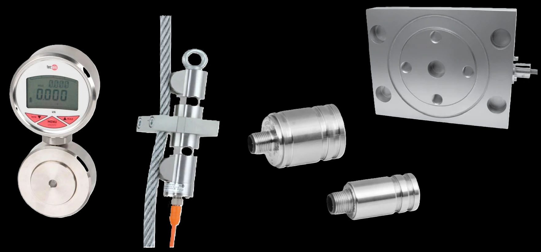
Specialty Force
Hydraulic compression/ring, wire‑rope, embedded‑strain & pillow‑block
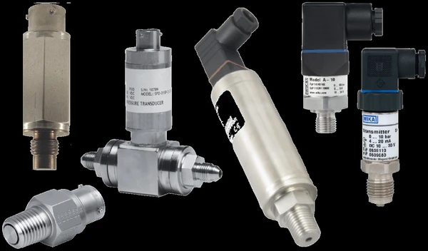
Pressure Transducers/
Transmitters
Transmitters
S‑10/A‑10, SP007, differential & dynamic
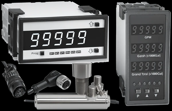
Displays, Amplifiers & Cables
Panel displays, in‑line & DIN‑rail amplifiers, digital indicators
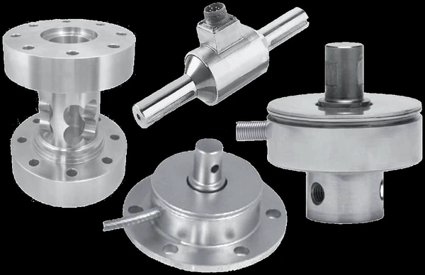
Reaction Torque Sensors
Flange & shaft mount — non‑rotating, no slip rings
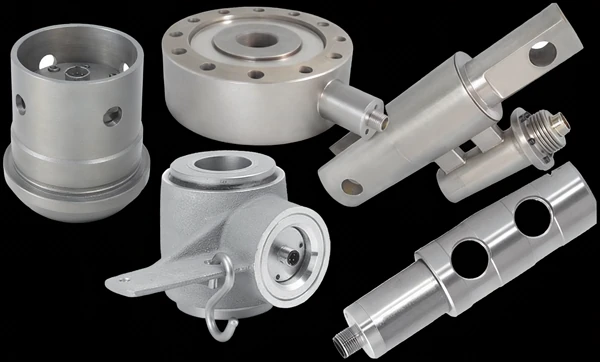
Oil & Gas Sensors
Hammer‑union, polished‑rod, coiled‑tubing & wireline
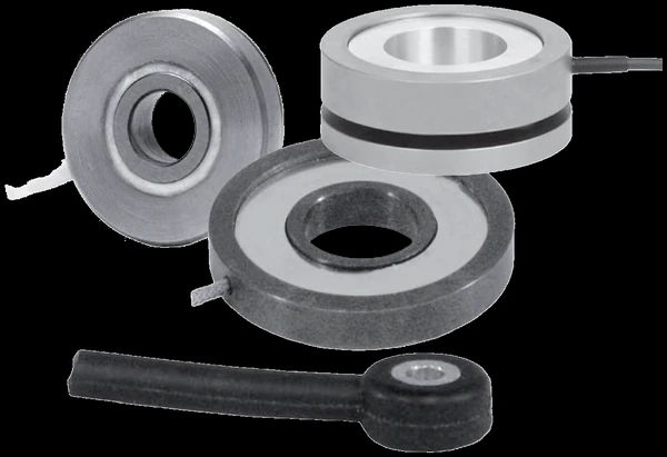
Thru-Hole & Ring Force
Donut washers, large‑ID ring & bolt sensors
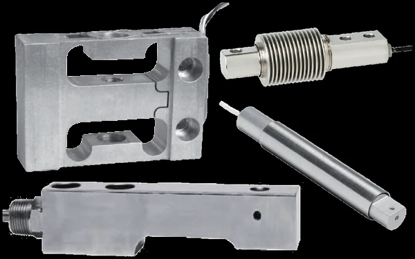
Beam-Type Load Cells
Bending‑beam, single‑point & parallelogram
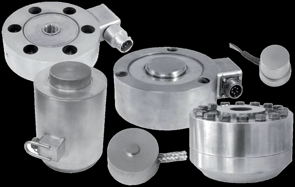
Round & Axial-Compression Load Cells
Pancake, canister & compact/button
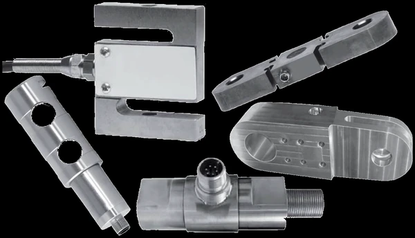
In-Line, S-Type & Load Pins
Rod‑end, S‑type & load pins — in tension, compression or universal
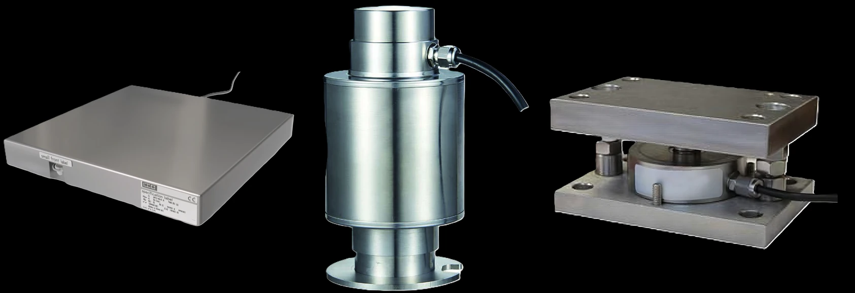
Weighing Systems
Liquid‑gas cylinder scales & self‑leveling load‑cell mounts
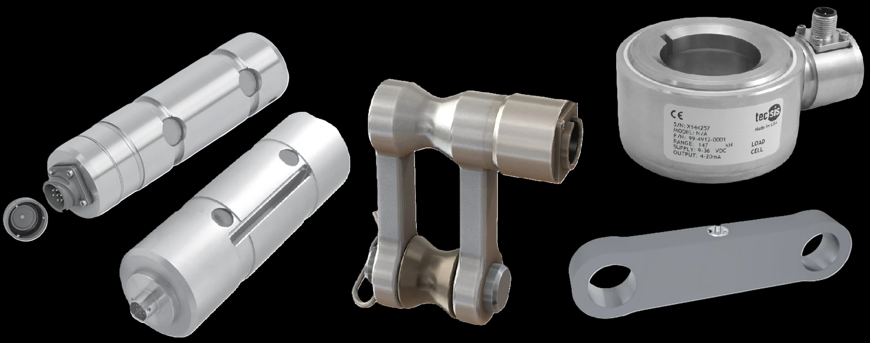
Crane & Heavy-Lift
Load pins & links, shackle, spreader & dual‑pin cells
Industries Served
Test & Measurement
Aerospace & Defense
Oil & Gas
Industrial Automation
Crane & Hoist
Automotive
Medical Devices
Water & Wastewater
FAQ: WIKA-ST force, pressure & torque sensors
How does a load cell or pressure transducer work?
Almost all of them work the same way underneath: a strain gauge measuring the deflection of an elastic metal element. The strain gauge takes one of two forms — bonded foil, where discrete foil gauges are adhesive-bonded to the element, or thin-film, where the gauge pattern is sputter-deposited directly onto the element with no adhesive (WIKA-ST uses both forms — thin-film on its F2301 thin-film force transducers and on parts of its pressure range, and bonded foil on most of its load cells; thin-film's molecular bond avoids the slow adhesive creep a bonded-foil design can show over time). Either way, when force or pressure is applied the element deflects by a tiny, repeatable amount and the gauges stretch or compress with it, changing their electrical resistance. Four gauges are wired into a Wheatstone bridge, so that deflection becomes a small, balanced voltage proportional to the load — typically expressed as millivolts of output per volt of excitation (mV/V). A load cell applies this to force; a pressure transducer/transmitter applies it to a diaphragm sensing pressure; a torque sensor applies it to a shaft or flange in twist. The differences between the families on this page are mostly about the shape of that elastic element and how it is packaged.
Load cell, load pin, or torque sensor — what is the difference?
They measure three different mechanical quantities. A load cell measures force — tension or compression — through a strain-gauged element you put into the load path; it is the most flexible and broadest-range option (the WIKA-ST range spans grams to 1,000 tons). A load pin measures force too, but it is the structural pin — you replace an existing clevis, sheave, or shackle pin with a strain-gauged equivalent, so you measure the load through hardware that is already there without adding fixturing; it is purpose-built for lifting, rigging, and crane safety. A reaction torque sensor measures torque — rotational force — at a fixed mounting flange, with no slip rings or telemetry needed, for test stands and motor characterization. The deciding question: is the force applied along a load path (load cell), through an existing pin (load pin), or as twist on a shaft (reaction torque sensor)?
How do I choose the capacity or pressure range?
The goal is to have the working load land in the upper-middle of the sensor's range — high enough for good resolution and signal-to-noise, with enough headroom that normal peaks and transients never exceed the rating. A common target is to size so the routine working load is roughly 50–90% of capacity. Two mistakes are typical: oversizing, where the real load uses only a sliver of the range and resolution suffers; and undersizing, where overload events damage the sensor or shift its calibration. Account for shock and dynamic peaks, not just the static load, and for side loads that an axial sensor isn't meant to see. If the application has both a small routine load and rare large peaks, say so — that is a case for either a higher-capacity sensor with good low-end resolution, a fatigue-rated design, and/or a built-in physical overload stop for force transducers.
What do ±0.25%, ±0.1%, BFSL, and FSO actually mean?
These are the accuracy terms on every datasheet, and they are worth decoding. FSO — full-scale output — means the error is quoted as a percentage of the sensor's full range, not of the current reading; a ±0.25% FSO sensor rated 10,000 lb can be off by ±25 lb anywhere in its range, which is a larger relative error at low loads. BFSL — best-fit straight line — describes how linearity is calculated: the error is measured against the straight line that best fits the calibration data, which usually gives a smaller, more favorable linearity number than other methods. A spec like ±0.1% marks a test-and-measurement-grade sensor (calibration standards, R&D); ±0.25–0.5% is the industrial standard grade (general process, OEM, lifting); ±0.05% FSO with a fatigue rating is the structural-qualification grade. When you compare two sensors, make sure they quote accuracy the same way — otherwise it is not a like-for-like comparison.
mV/V or amplified output (4–20 mA, 0–10 V) — which should I order?
A raw strain-gauge bridge puts out a small mV/V signal — millivolts per volt of excitation. That is the right output when it feeds a data-acquisition system or indicator with proper bridge conditioning, common on test benches; it is low-level, so it needs a clean, short, shielded run. An amplified output — 4–20 mA or 0–10 V — has the conditioning built in, either inside the sensor or in an external amplifier (available as an accessory), and reads straight into a PLC or DAQ with no bridge card. Use 4–20 mA for long industrial cable runs and noisy environments, where the current loop resists interference; use 0–10 V for shorter test-and-measurement runs; use IO-Link or a digital protocol for factory automation that wants bidirectional diagnostics and parameterization. Decide it from what is receiving the signal and how far away it is — most of these families offer the output as a configuration option.
Which load cell form factor — pancake, S-type, canister, button, donut, rod-end?
The form factor is chosen for how the load gets into the cell. Pancake / low-profile — a thin axial cell for compression or tension/compression; structural test, press force, calibration; capacities to 500,000 lb. S-type — the general-purpose tension/compression cell; hanging scales, inline force, web tension. Canister — a tall cylindrical body for high capacity; weighing and process to 750,000 lb (~375 short tons), environmentally sealed stainless. Button / subminiature — coin-sized compression cells for tight spaces such as robots, instruments, and medical devices. Donut / thru-hole — measures force through a bolt, rod, or pin without breaking the load path; bolt preload, clamping force. Rod-end / in-line — threads directly into the loading line, removing fixturing variability; actuators, cylinders, load frames. Tell us how the load is applied and how much room you have, and the form factor usually picks itself.
How do I measure pressure that spikes very fast?
Fast events — water hammer, valve and actuator slam, pipeline surge, seal burst, gun-chamber and combustion pressure — defeat an ordinary process transmitter, because its mechanical and electrical response is too slow to capture the peak before it is gone. These need a dynamic / high-frequency pressure transducer with a high natural frequency — the XPMD DynAstat, for example, responds from DC to 100 kHz, with a sensing element whose natural frequency runs from about 35 kHz up to 162 kHz depending on range. The rule for dynamic measurement: the transducer's natural frequency must sit well above the frequency content of the event you are trying to capture, or the reading will be distorted by the sensor's own resonance. Tell us the rise time or frequency of the transient and we size the natural frequency around it.
How do I measure differential pressure?
Differential pressure (Δp) is the difference between two points, and it is the basis for several measurements: flow across an orifice, the condition of a filter or strainer, liquid level in a sealed vessel, and pump discharge-versus-suction. A differential pressure transducer has two process connections and reports the difference directly. The spec that is easy to miss is line (static) pressure — the SP007 SPD wet/wet transducers, for instance, measure Δp ranges from 1 psid up to 500 psid while sitting on a line that may be at 500 psi static; the sensor has to withstand the full static pressure on both ports while resolving the small difference between them. So a DP selection needs two numbers, not one: the differential range and the maximum line pressure.
How do I install and mount a load cell correctly?
Most load-cell errors in the field are installation errors, not sensor errors. The core principle: get the load axial, centered, and free of side load. Most series are rated for axial force only — take an off-center (eccentric) or side load and the reading is wrong and the cell may be damaged; eccentric-loading sensitivity is a real spec for a reason. Where off-axis loading is unavoidable, WIKA-ST offers load-cell designs built to tolerate it. Practical points: use the manufacturer's mounting hardware and load buttons or rod ends so the load introduces cleanly; keep the loading structure stiff and aligned; on multi-cell weighing arrays, mount all cells coplanar so they share load evenly; protect the cell from shock during installation; and route the cable so it is not strained or chafed. Rod-end and in-line cells thread straight into the load line specifically to remove fixturing variability — a good choice where alignment is hard to guarantee.
How are load cells and pressure transducers calibrated?
Calibration establishes the relationship between applied load and output against a traceable reference. Force sensors are calibrated on dead-weight or reference-cell machines traceable to national standards; pressure sensors against dead-weight testers or reference transducers — and a test-and-measurement-grade calibration is typically ISO 17025 accredited with a documented uncertainty. Temperature compensation calibrates at multiple temperature points in an oven for corrective offsets in the process temperature range. Two field-useful features: shunt calibration, where a known resistor is switched across the bridge to produce a predictable output step, lets you verify the system (sensor plus cabling plus electronics) without applying a real load; and TEDS (IEEE 1451.4), an electronic datasheet chip in the sensor, lets a DAQ read the calibration data automatically for plug-and-play setup. Recalibrate on the interval your quality system sets — annually is common — and sooner after any suspected overload.
What is fatigue rating, and when do I need it?
A standard load cell is calibrated to be accurate; it is not necessarily built to stay accurate through millions of load reversals. A fatigue-rated force sensor is designed and constructed to hold its calibration through tens to hundreds of millions of fully reversed cycles — load swinging tension-to-compression repeatedly. You need it on durability and life-test rigs: aerospace structural qualification, seal and O-ring life testing, suspension and powertrain durability, hydraulic-actuator fatigue characterization. The XLP52/54 fatigue-rated precision pancake, for example, holds ±0.05% FSO linearity under full-reversal loading. If your application is a test stand that cycles continuously, specify fatigue-rated from the start — a non-fatigue cell will drift or fail, and you will lose test data before you notice.
How do I measure force in a lifting, rigging, or crane application?
The standard tool is the load pin — you replace an existing clevis, sheave, or shackle pin in the lifting gear with a strain-gauged pin of the same dimensions, so you measure the actual load through hardware that is already in the load path, with nothing added to fixture. Industrial load pins span roughly 1,100 lb to 200 tons, and key options for this work include ATEX/intrinsically-safe versions for classified environments, IP67 sealing for outdoor and marine exposure, and wireless or CANbus output where running a cable down a moving structure isn't practical. For container terminals, spreader-bar load cells in four-corner arrays support SOLAS verified-gross-mass weighing. The application details that drive the pick: the pin dimensions to match, the environment, and whether the readout has to be wireless.
How rugged are these sensors, and can they handle harsh or hazardous environments?
Industrial force and pressure sensors are built for it. Hermetically sealed, all-welded stainless construction keeps moisture and contaminants out — important because moisture ingress into a strain-gauge bridge is a leading cause of drift. IP67 ratings cover washdown and submersion; canister cells are environmentally sealed for subsea and offshore load monitoring. For classified areas, ATEX/intrinsically-safe variants are available on pressure transmitters and load pins. For sour oil-and-gas service, wetted parts are specified to NACE MR0175 (the Model 1502 hammer-union transducer uses Inconel X-750 to that standard). Temperature is the quieter variable — every sensor has a compensated operating range, and extended-temperature compensation is an option where the process runs hot or cold. Specify the environment up front and the sealing, materials, and certification get built in.
What is overpressure / overload, and what happens if I exceed it?
Every sensor has two ratings above its measuring range. Safe overload (or overpressure) — commonly around 150% of full scale, higher on some designs — is the load it can see without losing calibration; exceed it and the sensor may still work but its accuracy has shifted, often invisibly. The burst or ultimate rating is where the sensor is physically destroyed. The danger zone is the gap between them: a sensor that has been overloaded past safe but not to burst keeps reporting numbers that look plausible and are wrong. This is why sizing for the real worst case matters, and why any suspected overload event should trigger a recalibration before you trust the data again.
What drives the cost of force and pressure sensors, and what is the lead time?
WIKA Sensor Technology and tecsis are catalog/datasheet lines with no public price list — pricing is quote-only, configured per application. Cost scales with accuracy class (a ±0.1% test-and-measurement sensor costs well more than a ±0.5% industrial one), capacity, materials, hermetic sealing, hazardous-area certification, amplified versus raw output, and calibration documentation. On lead time, the workhorse general-industrial pressure transmitters (the WIKA S-10 and A-10) and configurable SP007 transducers have short lead times from stocked components; specialty, high-accuracy, and custom-configured units run longer.
Who invented the strain gauge and the load cell?
The bonded strain gauge — the foundation of modern electrical force and pressure measurement — was invented independently around 1938 by two Americans: Edward E. Simmons at Caltech and Arthur C. Ruge at MIT. Ruge's employer initially saw little commercial value in it; it went on to make precision electrical force measurement possible and is still the basis of the industry. Pressure measurement is older: the Bourdon tube mechanical pressure gauge was patented by Eugène Bourdon in 1849 and is still in service worldwide. The strain-gauge load cell and the electrical pressure transducer brought both into the era of analog and digital control; thin-film deposition later refined the strain gauge further, sputtering it directly onto the sensing element.
Application engineering question? Talk to Scott — send directly to Scott Prater at scott@pratertechnical.com, or call him directly at 917-580-0878 during business hours.
Territory Coverage

New York: Full state
Connecticut: Full state
Massachusetts: Full state
Rhode Island: Full state
New Jersey: Northern NJ
Pennsylvania: Eastern PA — Allentown–Philadelphia corridor
Connecticut: Full state
Massachusetts: Full state
Rhode Island: Full state
New Jersey: Northern NJ
Pennsylvania: Eastern PA — Allentown–Philadelphia corridor
Territory detail above applies to WIKA Sensor Technology and the legacy tecsis line (Force, Pressure & Torque). Other manufacturer lines have their own coverage — see each brand’s page.
Specifications compiled by Prater Technical Partners from WIKA Sensor Technology product datasheets.