Product Overview
A process air heater heats a flowing air or gas stream — it is installed in a plenum, duct, oven, or furnace, and forced air passes across electric resistance elements and leaves at a controlled outlet temperature up to 1200°F. The heater is custom-built to the airflow (SCFM) and required temperature rise, in one of three element styles — open coil (cheapest, lowest pressure drop, clean air only), finned tubular (tolerates moisture and uneven airflow, to 600°F), or tubular (any air quality, highest velocity, to 1200°F). Choose process air when you need to heat moving air or gas; for heating a liquid, the immersion and circulation builds are the answer.
Key Features & Benefits
- Three element styles so the heater fits the air, not the other way around — open coil, finned tubular, or tubular — each suited to a different mix of temperature, air velocity, and air cleanliness, so you are not forced to over-build or compromise. One platform covers clean low-cost duct heat through dirty high-velocity 1200°F process air.
- Custom-built to your duct, airflow, and temperature rise — Aspeq controls the whole design and build — elements, framing, enclosure, and controls — so the heater is sized to your SCFM and ΔT and dropped into your plenum or duct rather than forced from a fixed catalog box. The heater is engineered to the application, not selected around it.
- Individually replaceable sheathed elements — on the finned tubular and tubular builds the elements flange-mount with push nuts and pull one at a time, so a field repair is a single element, not the whole heater. Serviceable for the life of the equipment.
- Built to a UL/CSA element-listing file, CE on request — because the elements are built to Aspeq’s UL or CSA listing files the heater carries component recognition, and a CE self-certification is available on that construction — the documentation your equipment and your export markets expect. The listings travel with the build (see the approvals row for exactly what they mean).
- Single-source heater-and-control package — matched thermostats, thermocouples, airflow switches, and SCR or contactor control panels come from the same shop, so overtemperature and no-flow protection is engineered in rather than bolted on in the field. One vendor owns the heater, the controls, and how they behave together.
Specifications
- Operating principle
- Electric resistance (Joule) heating of a flowing air or gas stream. The heater is installed in a plenum, duct, oven, or furnace; forced air passes across the resistance elements and leaves at a controlled outlet temperature. Air may be recirculated (to cut power and heater size) or fresh (where ventilation of the process is needed).
- Element styles (open coil / finned tubular / tubular)
- Three element styles, each chosen against outlet temperature, air velocity, and air quality: Open coil — bare 80/20 Nichrome resistance coil exposed directly to the airstream; outlet air to 1200°F, max velocity 2500 SFPM, clean air only. Finned tubular — spiral-finned sheathed element; outlet air to 600°F, max velocity 5000 SFPM, tolerates moisture and non-uniform airflow. Tubular — sheathed element; outlet air to 1200°F, max velocity 8000 SFPM, virtually any air quality. The right style is set per application (see Design & Selection Considerations).
- Element & coil construction
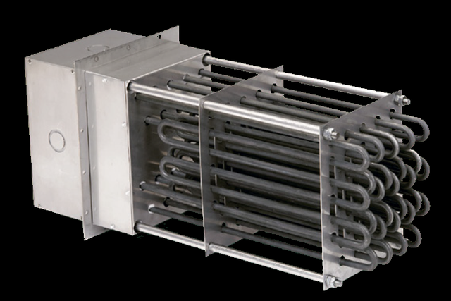
- Open coil: 80/20 Nichrome coils on rib-strengthened brackets with formed corner gussets and minimum bracket spacing to limit coil sag. Finned tubular: .475″ diameter, 304 stainless-steel elements with matching 304-SS corrugated fins 1-1/8″ O.D., individually replaceable, flange-mounted with push nuts. Tubular: .475″ diameter Incoloy 800 sheath, individually replaceable; recompressed bends eliminate hairline cracks in the magnesium-oxide insulation, and a unique bending pattern cuts the terminal count by more than half to lower terminal-box temperature.
- Framing & bracket materials
- Framing is matched to outlet temperature: galvanized steel up to 250°F outlet air, aluminized steel up to 600°F, and 304 stainless steel for higher temperatures (stainless framing is available on all constructions). Sheathed-element support brackets have flared / contoured openings so the elements expand and contract freely; 1/2″ steel rods tie the assembly into a rigid but expandable frame.
- Mounting / airflow orientation
- Open coil heaters mount horizontally only (for either horizontal or vertical airflow). Tubular and finned tubular heaters mount horizontally or vertically; when mounted horizontally the airflow may be horizontal or vertical, and (except 250°F units) they may be rotated 90° about a horizontal axis to fit the available space. The open framework allows universal mounting.
- Duct & flange mounting
- 250°F units attach to the duct or oven wall with sheet-metal screws through the base of the terminal box (integral channel frame, no separate flange). 400°F and higher units carry a heavy-gauge steel flange with pre-drilled mounting holes and bolt to the duct or oven wall. Flanged duct mounting and a flanged terminal box are available for attaching to external duct flanges with no internal support.
- Face dimensions & sizing
- The heater face (W × H) is sized so air velocity stays above the minimum for the chosen watt density — a larger face lowers velocity and forces a lower watt density. Standard listings span a wide range of W, H, and C (depth) dimensions; the heated length must sit entirely in the airstream so elements are not shadowed by an insulated wall (shadowed elements overheat). Face and depth are set with the order.
- Cold ends & flange insulation
- All heaters have 2″ cold ends as standard; longer cold ends are available to clear an oven wall or place the active element well into the airstream. 1″ of insulation in the terminal box is standard for outlet temperatures up to 750°F; 4″ of insulation below the mounting flange is standard on 1200°F construction (optional on others) and is extended for oven walls thicker than 4″.
- Maximum outlet air temperature
- Outlet air temperatures to 1200°F across the catalog range. Standard listings are tabulated at 250°F, 400°F, 600°F, 750°F, and 1200°F maximum outlet air. Open coil and tubular reach 1200°F; finned tubular is recommended to a 600°F maximum.
- Air velocity range
- Maximum air velocity is element-style limited: 2500 SFPM open coil, 5000 SFPM finned tubular, 8000 SFPM tubular. Standard heater listings assume a minimum velocity (e.g. 900 SFPM at the 250°F and 400°F listings); below the listed velocity a lower watt density must be selected.
- Watt density
- Watt density (watts per square inch of element surface) is the critical life factor — too high and the element fails early, too low and the heater is needlessly expensive. It is set by element construction, maximum outlet air temperature, and air velocity, per the catalog Table II below. Representative range: up to 65 W/in² for open coil / finned tubular at low outlet temperature, dropping to as little as 3 W/in² for tubular at 1200°F.
Maximum Watt Density (W/in²) by Outlet Temperature & Air Velocity
| Element style & outlet temp | At 300 SFPM | At 900 SFPM | At 2000 SFPM |
|---|---|---|---|
| Open coil — 250°F | 55 | 65 | 65 |
| Open coil — 600°F | 30 | 55 | 65 |
| Open coil — 1200°F | 10 | 15 | 30 |
| Finned tubular — 250°F | 45 | 65 | 65 |
| Finned tubular — 600°F | 30 | 45 | 65 |
| Tubular — 400°F | 30 | 30 | 45 |
| Tubular — 750°F | 13 | 25 | 45 |
| Tubular — 1200°F | 3 | 12 | 25 |
- Temperature rise & KW sizing
- Sized from the airflow in standard cubic feet per minute (SCFM) and the required temperature rise (ΔT) via the catalog KW formula KW = (SCFM × ΔT) / 3193 (SCFM referenced to 80°F and 15 psi; CFM at other pressure/temperature is corrected to SCFM first). The required KW and face area together set the model selection.
- Air-side pressure drop
- Air-side static pressure drop rises with velocity and with the space the elements occupy: open coil is lowest (often allowing a smaller fan motor), finned tubular is higher, and tubular is highest. The catalog publishes pressure-drop curves by element style and C (depth) dimension; an optional 40%-open inlet pressure plate evens out non-uniform airflow at the cost of added pressure drop.
- Air quality & contamination
- Open coil: clean air only — free of conductive particles and water spray (the coil is electrically live). Finned tubular: tolerates water droplets and conductive particles unless they build up between the fins. Tubular: usable with virtually any air quality (the live coil is sealed in the sheath, so contact shock hazard is eliminated).
- Wattage range
- Custom-rated to the application — standard listings run from a few kW to hundreds of kW per heater. Catalog custom builds include a single 550 kW heater (13 ft long, heating 39,000 SCFM to 610°F) and 240 kW tubular oven heaters ganged into multi-thousand-kW cure-oven systems. KW follows directly from the airflow and required temperature rise.
- Voltage / phase
- Standard listings are designed for 480 V, three-phase; voltages up to 600 V are available in single or three phase. Three power leads are brought to each circuit.
- Circuiting
- Standard listed circuits draw a maximum of 48 A (so 50 A contactors and 60 A fuses can be used); larger circuits up to roughly 300 A are available for large SCR controls or to cut the number of incoming conductors. On tubular and finned tubular builds the circuit count must stay consistent with the element count in the listing.
- Bus bars & terminals
- Removable bus bars secured with stainless-steel nuts and shakeproof washers; pressure connectors welded or bolted to the bus bars are furnished for field wiring of 8-gauge and heavier conductors. Stainless-steel terminal hardware and 10-32 threaded studs assure reliable connections.
- Thermostat / control options
- A built-in thermostat (adjustable 60–250°F) is available on heaters operating up to 150°F outlet air for automatic outlet control, as is a built-in combination thermostat / thermal cutout. For higher-temperature service, remote bulb-and-capillary thermostats mount in a cool location up to 8 ft away with a well into the airstream — available ranges 200–550°F and 300–700°F. A built-in sheathed thermocouple is available for high-temperature limit.
- Control integration
- Built-in contactors, fuses, control transformers, and disconnect switches are available on heaters up to 150°F outlet air for a single-source heater-control package; larger or higher-temperature loads pair with matched SCR or contactor control panels (panel instructions in the separate control-panel manual). Step and SCR schemes suit staged or tight-tolerance loads.
- Overtemperature & airflow protection
- Aspeq recommends overtemperature and low-airflow protection on every process-air heater. Four protective devices are offered: a thermal cutout (built-in thermostat set ~50° above normal, on 250°F units; a remote thermostat above that), a built-in thermocouple to a remote controller, a built-in airflow (differential-pressure) switch on units up to 150°F, and a fan-interlock relay tying the heater control circuit to fan power.
- Terminal box / enclosure
- A louvered terminal-box cover keeps connections and wiring at safe temperatures, with multiple concentric knockouts on all sides for convenient conduit entry. A dust-tight terminal box (welded stainless steel, hinged latched cover, Scru-tite hubs), an airtight or isolated junction box, and special materials (Monel, 316 SS, Inconel sheaths; stainless frames) are available for dirty, high-ambient, or corrosive environments.
- Approvals & listings
- Aspeq builds process air heaters per its UL or CSA element-listing files, so the heater is recognized as a UL or CSA component (the element assembly is in the listing file; final listing in the end application requires further testing of the installed equipment). CE is offered as a self-certification on assemblies built per the UL or CSA construction. Confirm the exact marking required for your equipment with the quote.
- Build & lead time
- Custom build-to-order — no published price list, quote-only. Lead times typically run about 3 to 14 weeks depending on configuration, hazardous-area documentation, and code-stamp requirements.
Common Applications
- Industrial ovens, furnaces, dryers, and autoclaves — paint baking, curing, baking, roasting
- Make-up air, booster, and standby heating in ducts and plenums
- Drying and dehydration — film, ink, varnish, textile, core, and agricultural-product drying
- Process air, exhaust-gas, and cryogenic-exhaust-gas heating
- Heat treating, annealing, and bonding / adhesive-cure ovens — including aerospace sealant and composite cure
- Chemical, pharmaceutical, semiconductor, and food-processing air heating
- Generator load banks and environmental / equipment test chambers
Design & Selection Considerations
- Pick the element style on the first four factors — cost, air quality, temperature, velocity — Indeeco’s own selection guidance is that these four usually decide it: open coil is cheapest and lowest pressure drop but needs clean air and tops out at 2500 SFPM; tubular handles dirty air and the highest velocities but costs the most and adds the most pressure drop; finned tubular sits between, capped at 600°F outlet. If one style wins those four, it is almost always the right pick.
- Open coil is electrically live — clean, dry air only — the bare coil offers low cost and quick response, but it must never see conductive particles, water spray, or possible contact by personnel or conductive material. Where the air is dirty, wet, or accessible, move to a sheathed (finned tubular or tubular) element instead — one catalog rebuild replaced shorted-out open coils with a tubular heater after fiberglass filings fouled the airstream. Air quality is the line that disqualifies open coil.
- Watt density is the make-or-break life spec — set it by temperature and velocity — too high a W/in² burns the element out early; too low drives up cost. It is fixed by element style, outlet temperature, and air velocity (the figures are in the specifications). A bigger heater face lowers velocity, which forces a lower watt density — so face size and watt density are picked together. Use the input form to tell us the airflow and we work backward to a safe density.
- Keep the airflow uniform across the face, or design for the non-uniformity — a heater too close to an elbow, fan, transition, or filter gets uneven airflow and hot spots — open coil is least tolerant of this. Where the layout cannot avoid it, an inlet pressure plate or non-heated zones even the air out (at some pressure-drop cost). Hot spots from bad airflow are a top field-failure cause — design the duct approach, not just the heater.
- Keep the heated length in the airstream — when a heater mounts through an insulated oven wall, any element shadowed by the insulation has no air over it and will overheat and burn out. Use insulation under the mounting flange and longer cold ends so the full heated length sits in the moving air. A burned-out element behind the wall is almost always a shadowing problem.
- Always protect against overtemperature and loss of airflow — an energized heater with stalled or blocked airflow overheats fast; a fan-interlock relay alone does not catch a stalled motor or a blocked duct. Pair a temperature limit (thermostat or thermocouple) with an airflow / differential-pressure switch. Two independent protections — over-temp and no-flow — are not optional on forced-air heat.
- Mind the pressure drop against the fan you have — element style and depth drive the air-side pressure drop, and the fan has to overcome it at the design velocity. Open coil can let you keep a smaller fan; a tubular build may need a bigger one. Size the fan and the heater together, not in sequence.
To size & select the right Heatrex process air heater:
Use the input form to send your airflow (SCFM, or CFM with its pressure and inlet temperature), the inlet and required outlet air temperature (or the temperature rise ΔT), the air quality (clean / moisture / conductive particles), the duct or plenum face dimensions and orientation, the available voltage and phase, and the control and overtemperature-protection requirements — and we’ll spec the right element style, watt density, and control package for your process air application.
Electric Heating Application Sheet ›Talk to an engineer directly — Scott Prater, Principal · 917-580-0878 · scott@pratertechnical.com
Specifications compiled by Prater Technical Partners from Aspeq Heating Group product datasheets.