Product Overview
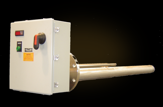
A tank heater maintains or raises the temperature of fluids and gases held in a storage tank using an open-coil pipe-insert element that slides into a 3″ pipe mounted in the tank. Heat passes through the pipe wall into the contents, so the resistance coil never touches the fluid and can be replaced without draining the tank. A low watt density spread over a large pipe surface heats even crude, heavy oils, asphalt, and other heat-sensitive materials gently — across a −300°F to 1000°F range. Choose a tank heater to heat the contents of a storage tank; for a flowing stream piped through a vessel, the circulation (inline) heater is the answer.
Key Features & Benefits
- Service the element without draining the tank — a burned-out coil is swapped while the tank stays full and the process seal stays intact, so an element change is a quick job instead of a shutdown-and-empty. The single reason most buyers choose this style over a direct-immersion heater.
- Gentle on heat-sensitive materials — a low-watt-density open coil spread over a large pipe surface gives uniform, low-intensity heat, so crude, heavy oils, pitch, and other temperature-sensitive fluids are warmed without local scorching. Heats the most stubborn materials without cooking them at the surface.
- The element never touches the fluid — heat passes through the pipe wall, so the resistance coil stays dry and out of the chemistry; the wetted pipe takes the corrosion and carries a heavy-wall corrosion allowance. The wear item is a length of pipe, not the heater.
- Mounts to the tank you already have — three different mounting methods bolt or weld the heater to almost any tank nozzle or wall opening (the options and sizes are in the specifications). Fits the tank instead of forcing a tank modification.
- Built-on controls or a matched remote panel — a built-on thermostat or DIN/SCR controller runs a self-contained heater, or a pre-wired Quick Ship contactor or SCR panel handles larger and tighter-tolerance loads with over-temperature protection. Standalone on a small tank; full process control when the load grows.
Specifications
- Operating principle
- Indirect electric resistance heating — an open-coil pipe-insert element (heavy-gauge nickel-chromium alloy wire on ceramic insulators) sits inside a 3″ NPS pipe that is mounted into the tank. Heat passes through the pipe wall into the surrounding fluid or gas, so the element heats the tank contents without ever contacting them. Used to maintain or raise the temperature of fluids and gases held in storage tanks.
- Mounting / installation
- Mounts to the tank by one of three methods: a 150# ANSI raised-face flange (300# rating available), a welded adapter box, or a custom rectangular flange. The heater pipes run horizontally into the tank — positioned just above the anticipated sludge level and below the minimum operating fluid level — so the mounting method and pipe count are specified with the order.
- Mounting sizes & configurations
- ANSI flange mounts: 6″ (1 pipe), 8″ (1–2 pipes), 10″ (1–3 pipes), and 12″ (1–4 pipes) at 150# (300# available). Adapter-box and rectangular-flange mounts each carry 4, 8, or 12 pipes in one or two rows. Pipe count is matched to the required kW.
- Heater pipe & corrosion allowance
- Open-coil elements install in 3″ NPS Schedule 40 pipe of sufficient wall thickness to keep the pipe from distorting under the heat; Schedule 80 is available for mildly corrosive fluids. The heavy pipe wall provides up to a 0.125″ corrosion allowance. Multiple pipes are furnished as the load requires.
- Open-coil element construction
- Open-coil heating element — heavy-gauge nickel-chromium alloy resistance wire supported by ceramic insulators that are fastened to a strip of heavy sheet metal. The low-watt-density coil spreads heat over a large pipe surface for uniform output. A 6″ cold (unheated) section at the terminal end keeps the heat away from the enclosure where the element exits the pipe.
- Element replacement
- The open-coil pipe-insert element withdraws from its 3″ pipe for replacement without draining the tank — the pipe stays sealed to the tank while the coil is pulled and a new one slides in, with no drain-down and no breaking of the wetted seal. Allow roughly the heater length of straight pull-out room ahead of the mount.
- Wetted materials
- The wetted parts are the mounting flange and the heater pipes (the coil is not wetted): carbon steel, 304 / 304L stainless steel, or 316 / 316L stainless steel, selected for the tank fluid’s chemistry and temperature.
- Cold (unheated) section length
- A 6″ cold (unheated) section at the terminal end of each element protects the terminal / control enclosure. Pipe-insert heaters are furnished with a 6″ or 12″ cold length to match a no-controls or built-on-controls build.
- Process / fluid temperature
- Maintains or raises the temperature of tank fluids and gases across a catalog range of −300°F to 1000°F, depending on fluid, watt density, and wetted-material selection.
- Watt density
- Low watt density by design, set to the fluid: 3 W/in² (standard for heavy oils and pitch), 9 W/in² (light oils and miscellaneous fluids), or 12 W/in² (water applications). The large pipe surface area spreads the load so even heat-sensitive materials are not scorched. Size the kW with a 1.2 safety factor per the catalog maintain / heat-up equations.
- Material & fluid selection
- Wetted material and watt density are chosen together against the tank fluid — carbon steel with 3 W/in² for heavy oils and pitch, stainless with 9–12 W/in² for lighter fluids and water (see the table below). Schedule 80 pipe is available for mildly corrosive service.
Wetted Material & Watt Density by Service
| Service | Watt density | Typical wetted material |
|---|---|---|
| Heavy oils / pitch / crude | 3 W/in² | Carbon steel (or 304 / 316 SS) |
| Light oils / misc. fluids | 9 W/in² | Carbon steel, 304 / 316 SS |
| Water | 12 W/in² | 304 / 316 stainless steel |
| Mildly corrosive service | per fluid | Schedule 80 pipe; 304 / 316 SS |
- Wattage range
- Sized from the tank surface area, insulation R-value, and required temperature rise per the catalog maintain and heat-up equations (an online sizing calculator is also published). Catalog listings run from 1.5 kW on a single-pipe flange heater to 288 kW on a 12-pipe adapter-box heater; multiple heaters serve very large tanks.
- Voltage / phase
- 115 V, 120 V, 208 V, 220 V, 230 V, 240 V, 277 V, 480 V, 575 V, and 600 V, single- and three-phase, per the catalog voltage-code table.
- Thermostat / control method
- Process control by built-on ON/OFF bulb-and-capillary thermostat (0–100°F, 60–250°F, or 200–550°F ranges), digital indicating thermostat (type J / K thermocouple or thermistor), a 1/16-DIN process controller, or SCR power control (DIN controller, or customer 4–20 mA / 0–10 VDC / 3–32 VDC pulse input). A thermowell for a customer sensor is also available. Heaters may be supplied with no controls for an external panel.
- Over-temperature protection
- Independent over-temperature protection: an ON/OFF high-limit thermostat (process sensor), a type J / K high-limit thermocouple (sheath sensor), or a limit controller with type J / K input (sheath sensor, to 999°F standard or 1600°F on the DIN limit controller, with manual reset). A thermowell for a customer high-limit sensor is available.
- Control panels & integration
- Matched remote Quick Ship control panels handle up to two 48 A circuits: a contactor panel (NEMA 4X fiberglass enclosure, 50 A contactor per circuit) for on/off duty, or an SCR panel (NEMA 4/12 painted steel, 50 A SCR power controller plus a 50 A safety contactor per circuit) for proportional control. Each panel is pre-wired, tested, carries a 120 VAC control transformer, and provides terminals for a customer remote interlock.
- Terminal / control enclosure
- Built-on terminal and control enclosures are NEMA Type 4 (weatherproof); the Quick Ship contactor panel uses a NEMA 4X fiberglass enclosure and the SCR panel a NEMA 4/12 painted steel enclosure, both rated for industrial and outdoor installation.
- Approvals & listings
- Quick Ship control panels are UL Listed. The user is responsible for an independent high-limit and a low-liquid / low-level interlock so the heater is never energized with the pipes uncovered, per the installation manual and local code.
- Build & lead time
- Custom build-to-order — no published price list, quote-only. Lead times typically run about 3 to 14 weeks depending on configuration, hazardous-area documentation, and code-stamp requirements.
Common Applications
- Crude-oil and heavy / fuel-oil storage-tank heating to hold pumpable viscosity — oil refineries, shale oil fields
- Petrochemical and chemical storage-tank temperature maintenance
- Asphalt and pitch storage tanks held at working temperature
- Fire-suppression / fire-water tank freeze protection
- Process and water tanks brought up from cold and then maintained at setpoint
- Heat-sensitive-material storage where a low-watt-density coil avoids surface scorching
Design & Selection Considerations
- Mount above the sludge, below the low fluid level — the heater pipes belong just above the anticipated sludge layer and below the minimum operating level, so the pipes stay covered in service and clear of settled solids. Get the elevation wrong and you either bake sludge onto the pipe or fire the heater dry.
- Never energize the pipes uncovered — because the heat is made in air inside the pipe, a pipe exposed above the falling fluid level overheats fast. A low-level / low-liquid interlock and an independent high limit are not optional. Interlock to proven fluid coverage and you remove the most common field failure.
- Set the watt density to the fluid, not the kW you want — heavy oils and pitch need the 3 W/in² coil; pushing 9 or 12 W/in² into them carbonizes the fluid against the pipe and shortens element life. Match the density to the material first, then add pipes to reach the kW. More watts per inch is not more capacity — it is a faster burnout.
- Spec the pipe schedule and alloy to the corrosion, not just the temperature — the pipe is the wetted, sacrificial part, so mildly corrosive service wants a heavier wall and/or a stainless pipe; the standard heavy wall already carries a corrosion allowance (in the specifications), and going to a thicker schedule or a stainless alloy buys more service life where the fluid is aggressive. The pipe is the part the fluid attacks — size its wall and alloy deliberately.
- Size for maintain AND heat-up — a tank that must be brought up from cold needs the heat-up kW (mass, specific heat, time) added to the maintain kW (surface area, insulation R-value, ambient). Sizing on maintain alone leaves a tank that holds temperature but never reaches it on schedule. Use the input form to tell us the heat-up time you need, not just the setpoint.
- Insulate the tank — the R-value drives the kW — the maintain load is set by the tank surface area and its insulation R-value; an uninsulated steel tank is treated as R-0.5 and demands far more kW. A modest jacket can cut the heater (and the running cost) dramatically.
- Leave pull clearance at the flange — the open coil withdraws horizontally from its pipe for service — leave roughly the heater length of clearance in front of the mounting flange at the layout stage. Easy to forget on the tank drawing, expensive to discover at the first element change.
To size the right Heatrex tank heater:
Use the input form to send your tank fluid or gas and its maintain or heat-up requirement — the tank dimensions and insulation R-value, the temperature to hold (and the start temperature and heat-up time if it must be brought up from cold), the minimum ambient, the setpoint and over-temperature limit, the wetted-material and corrosion requirement, available voltage and phase, and the mounting (ANSI flange, adapter box, or rectangular flange) — and we’ll size the kW, pick the watt density, and spec the right Aspeq tank heater and control package.
Electric Heating Application Sheet ›Talk to an engineer directly — Scott Prater, Principal · 917-580-0878 · scott@pratertechnical.com
Specifications compiled by Prater Technical Partners from Aspeq Heating Group product datasheets.