Product Overview
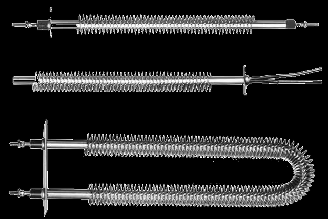
A tubular heating element is the OEM building block of electric heating: a nickel-chrome resistance coil centered in a metal sheath packed with compacted magnesium oxide, with cold pins giving an unheated terminal length. It is supplied as a bare element — round (0.200″–0.625″) or oval, one-pass or two-pass, finned or unfinned, in a sheath alloy from copper through Inconel — to be clamped, inserted, cast in, immersed, or used in air. Finned tubular adds a helically wound fin for air and gas heating. Choose the element when you are designing the heat into your equipment; for a packaged heater with its enclosure and controls, see the assembled-heater series.
Key Features & Benefits
- The OEM building block, formed to your part — this is the bare element, not a packaged heater — bent on CNC equipment to fit your platen, duct, tank, or casting, finned or unfinned, one-pass or two-pass. Start from the element when you are designing the heat in, not bolting a finished heater on.
- A sheath alloy for the medium, from water to 1800°F gas — the alloy menu spans copper for cool water up through Inconel for high-temperature air, each matched to the fluid chemistry so the sheath does not corrode out (the per-alloy limits and per-fluid picks are in the specifications). The element survives the medium because the sheath was chosen for it.
- Finned when you are heating air, bare when you are not — a helically wound fin multiplies the surface so a finned element runs a cooler sheath in low-pressure, low-temperature air; bare elements take the high temperatures, compressed gas, and lint-laden streams where fins would clog. Pick the surface to the airstream and the element runs cooler and lasts longer.
- A termination and seal for the terminal environment — studs, quick-connects, or weld-nuts; silicone, mica, or ceramic insulators; epoxy, RTV, or a hermetic seal against moisture — mixed and matched to the terminal-end temperature, voltage, and wet-or-dry exposure. The end that fails first is the terminal end; this is where it is engineered.
- UL Recognized, CSA, and certifiable to MIL — the element drops into UL- or third-party-listed equipment as a Recognized component, is CSA approved, and can be certified to military and customer specifications — so it clears the OEM’s own listing without a fight. The component approvals your finished-equipment listing needs, already in place.
Specifications
- Operating principle
- Electric resistance (Joule) heating — a coil of high-grade nickel-chrome resistance wire is precisely centered in a heavy-gauge metal sheath that is then filled with granular magnesium oxide and roll-compacted, so the MgO insulates electrically while transferring heat rapidly from the coil to the sheath. Cold pins welded to the coil at each end give an unheated length near the terminals. The element is the OEM building block — it heats by direct contact, immersion, or convection depending on how it is mounted.
- One-pass / two-pass construction
- One-pass — a straight coil with a terminal at each end; a straight one-pass element needs a flexible electrical connection at one end to absorb thermal expansion. Two-pass — a U-bent coil with both terminals at one end and the opposite end sealed by welding or silver soldering, so it can be rigidly mounted at one end. Both are available straight, formed, finned, or unfinned. Bends are recompacted (repressed) after forming to restore MgO density.
- Finned construction
- A corrugated metal fin is helically wound onto the tube and furnace-brazed or mechanically attached to extend surface area for air and gas heating. Standard fin density is 5 fins per inch; 8 fins per inch is available for lower sheath temperatures. Fin thickness is 0.015″; overall fin diameter is the sheath diameter plus twice the fin height (fin heights of 0.25″ or 0.32″ per the diameter / material). Finned diameters cover the 0.250″–0.625″ subset (Table II).
- Sheath diameters
- Round sheaths in 0.200″, 0.250″, 0.260″, 0.315″, 0.375″, 0.430″, 0.475″, 0.490″, and 0.625″ nominal O.D., plus a 0.235″ × 1.00″ oval (Table I). Multi-stage rolling holds a true round cross-section and a consistent diameter — important when the element is inserted into a machined hole. Heatrex offers the same diameter menu (0.200″–0.625″).
- Sheath materials & max temperature
- Selected by fluid chemistry and maximum temperature, each with a maximum sheath temperature: Copper (350°F), Steel (750°F), copper-plated steel (750°F), Titanium (750°F), Monel (900°F), 304 / 316 / 321 stainless steel (1400°F), Incoloy 800 and Incoloy 840 (1700°F), and Inconel 600 (1800°F). Not every alloy is offered in every diameter — the diameter / material matrix is in Table I.
- Sheath wall thickness
- Standard sheath wall 0.018″ to 0.049″ depending on diameter and material (e.g. 0.018″/0.025″/0.028″ on the 0.315″ element, 0.035″ on the 0.475″). Where multiple wall thicknesses are listed for a diameter, the standard wall is confirmed at order entry.
- Forming & bending
- Straight single-pass elements bend to virtually any configuration on CNC bending equipment; submit a drawing for a configuration not in the standard figure set. To protect the MgO, bends are repressed when the center-to-center spacing falls below a diameter-specific value (e.g. 2″ for the 0.475″ element). Minimum bend radius is material- and diameter-specific (Table VI) — for example a 0.475″ 304 SS element bends to a 0.5″ radius on a 180° bend.
- Sheath & cold-end lengths
- Sheath lengths from a 6″ minimum up to a diameter-dependent maximum (to 359″ on the smaller diameters; e.g. 333″ on 0.475″ round). Cold (unheated) ends are 1.5″ minimum, up to 45″ on the larger diameters. Length tolerance is 1% of overall sheath length (1/8″ minimum); heated-length tolerance 1% (1/2″ minimum). A straight finned element will expand roughly 1/8″ per foot of heated length.
- Voltage & current ratings
- Maximum voltage 240–600 V and maximum current draw 15–60 A, both diameter-dependent (the 0.475″ element rates to 600 V / 55 A). Wired single- or three-phase by the assembly that incorporates it.
- Wattage tolerance
- +5% / −10% on rated wattage; resistance is held within the per-diameter ohms-per-inch range listed in Tables I and II. Tighter tolerances and hydrostatic or special testing are available to MIL and customer specifications.
- Watt density
- Watt density (W/in² of sheath surface) is the single most important life factor — calculated as element wattage ÷ (π × sheath diameter × heated length). It is set by the maximum outlet temperature, the type of fluid, and the flow rate (or, in air, by velocity). The lowest practical watt density gives the longest element life; Table III lists the maximum recommended density per fluid.
- Sheath temperature (air / gas)
- For air and gas, Charts A–C give the resulting sheath temperature across a range of watt densities and airflow velocities (based on atmospheric air at a 75°F inlet; sheath temperature rises with inlet temperature). Finned elements run cooler sheaths at a given density — the extended surface is why they are preferred for low-pressure, low-temperature air and natural convection.
- Fluid & sheath selection
- Table III recommends a sheath material and a maximum watt density for each heated fluid across roughly 200 process media — water, glycols, fuel and heat-transfer oils, plating and process chemistries, and gases. An incorrect sheath material corrodes and destroys the element; too high a watt density carbonizes or chemically breaks down the fluid. Representative rows are below; the full table travels with the quote.
Watt Density & Sheath Material by Heated Fluid (representative rows)
| Heated material | Max temp | Max W/in² | Recommended sheath |
|---|---|---|---|
| Process / potable water | 212°F | 50–75 | INCONEL 600, INCOLOY 800, 304/316 SS |
| Demineralized water | 212°F | 50–75 | INCONEL 600, INCOLOY 800 |
| Ethylene glycol (100%) | 390°F | 5–10 | Carbon steel, copper, 304/316 SS |
| Light fuel oil (No. 1&2) | 200°F | 15–20 | Carbon steel, INCOLOY 800, 304 SS |
| Heavy fuel oil (Bunker B&C) | 160°F | 5–12 | Carbon steel, INCOLOY 800, 304 SS |
| Lubricating / machine oil | — | 23–26 | Carbon steel, copper, INCOLOY 800 |
| Dowtherm A (heat-transfer) | 400°F | 3–5 | Carbon steel, INCOLOY 800, 304 SS |
| Therminol 66 | 650°F | 10–15 | INCOLOY 800, INCONEL 600 |
| Caustic soda (NaOH) | 180°F | 25–40 | Carbon steel, nickel |
| Sea water / salt brine | 212°F | 50–75 | MONEL 400, titanium, INCOLOY 800 |
| Sulfuric acid (10–50%) | — | 15 | C276 Hastelloy |
| Process air / gas (forced) | — | 10–30 | INCOLOY 800, INCONEL 600 (per charts A–C) |
- Heating metals (clamped / cast-in)
- For clamped, drilled-in, or cast-in metal heating, Table IV gives recommended watt densities and sheaths by maximum metal temperature — for example 20 W/in² on steel clamped to a flat surface at 200°F, up to 15 W/in² on Incoloy in machined grooves at 800°F. Allowable density varies with element fit and metal thickness.
- Terminals
- Threaded stainless-steel stud (standard, 600 V, with SS nuts and washers for field wiring; hold the terminal against rotation when wiring), quick-connect (1/4″ plated-steel tab, 30 A max), and weld-nut (internally threaded tab with terminal screw). Standard thread is 6-32 on the 0.250″/0.260″ diameters, 10-32 on all others. Field wiring is torqued per the IOM (e.g. 20 in-lb on a 10-32 stud).
- Terminal insulators
- Silicone rubber (standard, terminal temperatures to 400°F), mica (to 900°F), and ceramic (to 1400°F); 1/4″ thick to 250 V, 1/2″ thick to 600 V. The insulator and seal are matched to the application’s temperature, voltage, and atmosphere.
- Moisture seals
- Element ends are sealed against moisture, which rapidly degrades the MgO insulation: epoxy barrier (low-to-moderate humidity, to 266°F on 0.315″ and larger), RTV barrier (to 392–428°F), and a ceramic-to-metal hermetic seal for an absolute moisture seal to 1000°F. For wet / defrost service, epoxy-filled metal-cup and over-molded Neoprene / Valox defrost terminals are available (UL Recognized File SA3254).
- Lead-wire options
- Where leads replace studs: Neoprene (90°C, abrasion / oil resistant), PVC (105°C), silicone-rubber / glass-braid (SRG, 200°C, the standard lead), TGGT (PTFE / glass, 250°C), and mica-glass (MGT, 450°C) — all rated to 600 V. A grounding strap is offered on long straight single-pass finned elements to suppress secondary-current arcing.
- Installation methods
- The element accepts every standard OEM mounting: clamped to a surface (low temperature, leave the element free to expand), inserted into drilled holes or machined grooves (drill 0.003″–0.005″ oversize, lubricate before insertion), cast into metal for uniform heat, immersion (threaded fitting or bent over the tank wall; keep the heated section fully submerged), radiant (SS or Incoloy sheath with a reflector), and air heating (finned or unfinned, forced or natural convection; support elements over 24″ on 2–3 ft centers).
- Mounting accessories
- Two factory accessory families hold the element in place: threaded fittings (hex or round shoulder, brass / steel / stainless, silver-soldered, welded, or staked to the sheath, furnished with nuts and optional gaskets / washers) and stainless mounting plates (Type I for 2-1/2″ C-C U-bent, Type II for straight or two-pass, for air-stream and non-immersed service). One-pass elements take a fitting at each end; two-pass take one.
- Approvals & listings
- UL Recognized under UL 1030 (File E78533); refrigeration-defrost elements UL Recognized under File SA3254. CSA approved (contract 151727, Class 2871-02 / 2871-82). CE marking available on request. Elements can be certified to MIL-H-22577 Rev C and MIL-PRF-22594 Rev C and to customer specifications. All elements are dielectric-tested per UL 1030 before shipment.
- Quality control
- Highest-grade MgO, each batch checked to ASTM D3347 (tap density) and ASTM D2755 (sieve analysis) for high, uniform insulation density; multi-stage rolling for a true round cross-section and consistent diameter. Bends are recompacted to restore MgO density and eliminate hairline cracks.
- Build & lead time
- Custom build-to-order — no published price list, quote-only. Lead times depend on diameter, sheath material, forming, and any MIL / special-test certification.
Common Applications
- OEM heating sub-assemblies — the element supplied to an equipment builder who packages it
- Platen, die, and mold heating — clamped, inserted in drilled holes / machined grooves, or cast in
- Forced- and natural-convection air and gas heating — finned for low-temperature air, unfinned for hot or dirty streams
- Immersion heating of liquids — threaded-fitting or over-the-side element forming the heart of an immersion heater
- Radiant process heating — stainless or Incoloy sheathed elements behind a reflector
- Refrigeration and freezer defrost — sealed defrost-terminated elements (UL File SA3254)
Design & Selection Considerations
- Watt density and sheath alloy are the two life-or-death picks — too high a watt density carbonizes a fluid or burns the element out; the wrong alloy corrodes the sheath through. Both follow from the medium and its maximum temperature — give us the fluid and the temperature and we work back to a safe density and alloy (the per-fluid table is in the specifications). Almost every early element failure traces to one of these two.
- Let a straight element expand — or it will tear its own seal — a heated sheath grows lengthwise, so a single-pass straight element has to be free to move at one end; clamp it rigidly at both ends and the thermal growth works the terminal seal loose over time. Two-pass construction sidesteps this by anchoring only one end. Plan the expansion path before you fix the mounting.
- Match the terminal seal to the wet-and-hot reality, not the average — epoxy holds to 266°F in modest humidity; a wet defrost or washdown end needs the epoxy-cup or hermetic seal; a high-temperature terminal needs RTV or a hermetic seal and a mica or ceramic insulator. Pick for the worst case the terminal sees. Moisture into the MgO is the classic slow death — seal for it.
- Drilled-hole fit decides how hard you can drive a cast-in or clamped element — in metal heating, the achievable watt density depends on how tightly the element seats in the machined opening and on metal thickness — a loose hole runs the sheath hot. Hold the recommended clearance, lubricate on assembly, and de-rate per Table IV. The fit, not the catalog number, sets the safe density.
- Megger and bake before energizing after storage — the magnesium oxide is hygroscopic, so an element off the shelf can read low insulation resistance. Megger it with a 500 VDC tester; if it reads under 1 megohm, bake at 250°F or energize at reduced voltage in air until it recovers. A “bad” new element is usually just damp MgO.
- These are bare elements — the safety controls are the integrator’s job — an element on its own has no thermostat, high-limit, or ground-fault protection; the equipment builder must add a disconnect, branch-circuit and short-circuit protection, backup temperature limiting, pressure relief where applicable, and proper grounding per the IOM and the NEC. The element is a component; the protected system is built around it.
- Bare vs finned in air is a contamination call as much as a thermal one — finned elements give the most surface for clean low-temperature air, but lint, straw, or other airborne debris catches in the fins; for dirty streams, compressed gas, or service over 400°F, unfinned elements are the safer pick. If the airstream is dirty, the fins become a liability.
To spec the right Indeeco tubular or finned element:
Use the input form to send the medium being heated and its maximum temperature, the required wattage and voltage, the diameter and sheath material (or the temperature / chemistry so we can pick them), whether you need it finned, one-pass or two-pass, the formed shape or a sketch, the cold-end length and termination / seal, and the mounting method — and we’ll spec the right Aspeq element for your assembly.
Electric Heating Application Sheet ›Talk to an engineer directly — Scott Prater, Principal · 917-580-0878 · scott@pratertechnical.com
Specifications compiled by Prater Technical Partners from Aspeq Heating Group product datasheets.