Product Overview
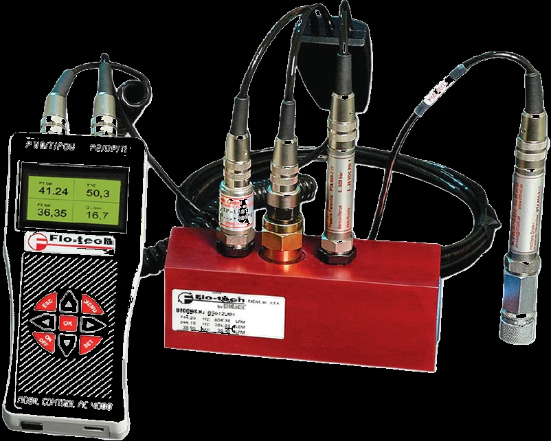
The MC4000 is the electronic handheld in the Flo-tech line — a battery-powered analyzer with five sensor inputs (turbine flow, two pressures P1 and P2, temperature, and an RPM pickup), four of them shown together on a back-lit graphic LCD. It reads to ±1% of reading at 32 cSt with ±0.2% repeatability and a turbine response under 200 ms, and it does what a gauge cannot: a 2.5 MB datalogger stores up to 80,000 time-stamped samples across every channel, two 1 ms fast-transient recorders on P1 catch pressure spikes a needle never settles on, and hydraulic horsepower is computed automatically from pressure and flow as hp or kW. Three-point flow calibration trims the turbine to the fluid, and stored records upload to a PC over USB through the MC4CON utility. Choose it when the job needs recorded data, transients, RPM, or computed power — for an instant standalone check, the gauge-based PFM6 is the field counterpart.
Key Features & Benefits
- Five inputs, four readings at once — turbine flow, two pressures, temperature, and an RPM pickup connect to one instrument; four of them display together in four LCD windows, so a pump or motor circuit is characterized from a single handheld instead of a bench of separate gauges. One tool reads the whole circuit.
- Catches the pressure spike a gauge misses — two fast-transient recorders watch P1 at 1 ms depth, programmable trigger, 240,000-measurement capacity, so a relief-valve crack or a shock spike is recorded as it happens — the kind of event that never settles on a needle. See the transient, not just the steady state.
- Records the run, not just the moment — the 2.5 MB logger holds 80,000 dated, time-stamped readings from every channel plus computed power, and uploads over USB to a PC through MC4CON — baseline data you can trend, file, or hand off. Diagnostics you can keep.
- Reads out hydraulic power directly — the analyzer multiplies live pressure by flow and shows the result as hp or kW, so pump and motor efficiency is read on the screen rather than worked out by hand — the basis for efficiency baselining and PM trending. Power without the math.
Specifications
- Measurement principle
- Turbine flow with multi-sensor electronics — the passing fluid spins a bladed rotor at a speed proportional to flow rate while integral pressure and temperature sensors read the same point; the analyzer scales, logs, and computes from all channels at once.
- Measured parameters
- Flow, two pressures (P1 / P2), temperature, and RPM — up to four readings shown together in four LCD windows, in US or DIN process units.
- Flow ranges
- By turbine port: SAE 8 / G¼ 0.4–7 gpm (1.5–26 lpm), SAE 12 / G¾ 1–40 gpm (4–151 lpm), SAE 16 / G1 4–80 gpm (15–302 lpm), SAE 20 / G1–¼ 8–160 gpm (30–605 lpm).
- Accuracy
- ±1% of reading at 32 cSt (electronic sensor); the display reads to ±0.1% ±1 digit from midrange (16-bit A/D).
- Repeatability
- ±0.2%.
- Turbine response time
- Turbine response ≤200 ms.
- Calibration reference fluid
- 0.876 SG / 150 SUS (32 cSt) hydraulic oil — the line’s reference fluid; on-board three-point flow calibration trims the turbine to the working fluid.
- Functional viscosity range
- Functional ~2 to 110 cSt (25 to 500 SUS); calibration shifts as the fluid thickens, so a reading far from 32 cSt needs the operating viscosity confirmed.
- Operating / fluid temperature
- Fluid −4 to 300°F (−20 to 150°C); ambient −22 to 158°F (−30 to 70°C), 0–90% non-condensing.
- Maximum pressure
- 5800 psi (400 bar) max; 5000 psi (345 bar) on the SAE 20 and G1–¼ sizes. Pressure-sensor ranges are ordered per channel (870 / 1450 / 3625 / 5800 psi).
- Body / housing materials
- Turbine housing 6013-T651 anodized aluminum; pickup housing nickel-plated; pressure-sensor case 300-series stainless.
- Wetted materials
- T416 stainless rotor, T303 stainless rotor shaft, 440C stainless bearings, 6061-T6 aluminum supports and plugs, Buna-N seals; pressure-sensor diaphragm 17-4 PH stainless.
- Sensor inputs
- Five — turbine flow (10 mV–5 V P-P sine, 0.5–10 kHz scalable), two pressures (dual 4–20 mA, P1 / P2), temperature (Pt-100, −50 to 500°C), and RPM (5–24 V active pickup, 30–60,000 rpm); four connect at once.
- Computed values
- Hydraulic horsepower — computed automatically from pressure × flow, displayed as hp or kW. Peak & valley capture holds the P1 / P2 maxima and minima; Tare zeroes each pressure channel independently.
- Datalogging / recording
- 2.5 MB internal memory logs up to 80,000 samples across all four channels plus computed power, date, and time (sample rate 1 s to 120 min). Two fast-transient recorders sample P1 at 1 ms, 240,000-sample capacity, with a programmable 0–100% trigger for pressure spikes.
- Outputs
- USB data port — stored records upload to a Windows PC through the MC4CON utility (bi-directional: upload records, download settings).
- Display
- Back-lit graphic LCD, 128×64 pixels (auto-off backlight); nine-key front panel; pressure units bar or psi; English plus French, German, Italian, or Spanish (set at order).
- Power
- Rechargeable 6 V, 2 Ah battery; 100–240 V AC charger (international or North American cord).
- Battery / run time
- About four hours per charge with two pressure sensors connected and the backlight off.
- Calibration certificate
- Optional — factory NIST-traceable calibration certificate (5-point or 10-point), ordered with the analyzer.
- Dimensions / weight
- 8.70 × 3.62 × 1.62 in (221 × 92 × 41 mm).
Common Applications
- Pump and motor efficiency baselining — flow, pressure, and computed hp/kW captured in one pass
- Relief-valve and shock testing where the fast-transient recorders catch the 1 ms pressure spike
- Hydrostatic-drive and closed-loop evaluation, and power-steering diagnostics
- Test-stand and hydraulic-power-unit monitoring with logged, time-stamped data
- Preventive-maintenance trending — periodic baselines filed and compared over a machine’s life
Design & Selection Considerations
- Match the turbine port to the flow range — the analyzer reads whatever turbine you connect, but accuracy holds only within that turbine’s range — SAE 8 covers 0.4–7 gpm, SAE 20 covers 8–160 gpm. Size the turbine to where the circuit actually runs; a flow that sits at the bottom of an oversized turbine reads poorly. Use the input form to tell us the expected flow and we pick the port.
- Viscosity moves the calibration — the turbine is calibrated on 0.876 SG / 150 SUS (32 cSt) oil and holds across roughly 2 to 110 cSt, but like any turbine its calibration shifts as the fluid thickens. For work far from 32 cSt the three-point flow calibration trims it — tell us the operating viscosity and we set the right accuracy expectation.
- Order the pressure ranges to the circuit — P1 and P2 are ordered per channel (870, 1450, 3625, or 5800 psi); the instrument tops out at 5800 psi, or 5000 psi on the SAE 20 and G1–¼ sizes. A sensor sized well above the working pressure trades resolution for headroom, so match the range to the duty.
- Traceable readings need the certificate — when the data has to stand up — warranty work, efficiency contracts, lab use — order the analyzer with a NIST-traceable 5-point or 10-point calibration certificate; configuration, scaling, and comms setup are available as an optional, quoted service.
To size & select the right MC4000 analyzer:
Use the input form to tell us the hydraulic circuit, the flow range and port size, the working pressure and temperature, the fluid and its operating viscosity, and what you need the reading to do — a live field check, recorded data, or a permanent stand — and we’ll match the tester, sensor, and display, confirm the output and any NIST-traceable calibration, and price it — with programming and commissioning available as an optional, quoted service.
Flow Meter Application Sheet ›Talk to an engineer directly — Scott Prater, Principal · 917-580-0878 · scott@pratertechnical.com
Specifications compiled by Prater Technical Partners from Badger Meter Flo-tech hydraulic test & diagnostics product literature.