Product Overview
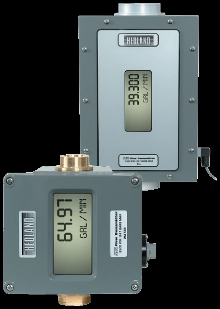
The Hedland MR transmitter adds non-contact electronics to the variable-area meter: a magnetic sensor tracks the spring-loaded piston, and a signal-conditioning board displays flow rate and accumulated total in user-selectable units while driving one proportional analog output. That output is field-selectable as 0–5 V DC, 0–10 V DC or 4–20 mA, one mode at a time. The readout is a dual-line LCD — a tall 8-digit numeric line for rate / total over an 8-digit alphanumeric line for units and setup — and the board rotates 180° to suit the mounting. Power it as a two-wire 4–20 mA loop or from an external DC supply for the voltage outputs, sealed in a NEMA 12 / 13 (IP52/54) enclosure. It rides on a standard Hedland meter body — aluminum, brass or 316 stainless matched to the fluid, liquid or gas, in ¼ to 1½ in. ports. The MR itself has no relays; for setpoint alarms, a scaled panel readout or fieldbus comms, feed its signal to the optional F6700 / F6750 remote display. For a simple trip contact instead of a continuous signal, use the Flow-Alert switch.
Key Features & Benefits
- Rate, total and a signal out — shows flow rate and running total on the display while driving a proportional output to a PLC, DCS, chart recorder or data logger
- Selectable analog output — one output, field-selectable as 0–5 V DC, 0–10 V DC or 4–20 mA, to match the receiver — only one active at a time
- Non-contact sensing on a proven meter — a non-contact magnetic sensor reads the spring-loaded piston of the variable-area meter, so the electronics add a signal without adding a leak path or wear part
- Dual-line readout — a tall numeric line shows rate or total in user-selectable units over a smaller line that names the units and walks the setup menu; the display board rotates 180° for the mounting
- Loop- or externally powered — run it two-wire loop-powered on 4–20 mA, or from the target / external supply for the voltage outputs
- Built on the right body for the fluid — aluminum, brass or 316 stainless meter body matched to the service — liquid or gas
Specifications
- Function
- A direct-reading variable-area meter with an electronic signal-conditioning circuit that displays flow and sends a proportional analog output to a control system
- Measurement principle
- Variable area — a spring-loaded piston and orifice meter the flow; the signal-conditioning board linearizes it for display and analog output
- Compatible fluids
- Liquid or gas service (meter body selected for the fluid — aluminum, brass or 316 stainless)
- Measurements
- Flow rate and accumulated total, each in user-selectable engineering units
- Analog output
- One proportional output, field-selectable as 0–5 V DC, 0–10 V DC or 4–20 mA — only one active at a time. Voltage outputs drive ≥10,000 Ω; 4–20 mA drives ≤1,000 Ω. Output resolution 1:4000
- Display
- Dual-line LCD — an 8-digit 0.70 in. numeric line for rate / total plus an 8-digit 0.35 in. alphanumeric line for units and setup; fixed or toggling rate / total. Display board rotatable 180° for viewing
- Power
- Loop-powered on 4–20 mA (30 V DC max); 0–5 V output 10–30 V DC and 0–10 V output 12–30 V DC, each at 0.75 W max from the target / external supply. 25 mA max consumption; reverse-polarity and current-limit protected
- Meter accuracy
- Meter ±2% of full scale; repeatability ±1%
- Flow ranges
- Set by the meter family and port size — each port size offers several full-scale ranges in the selected fluid; specified per order
- Port / line sizes
- ¼ to 1½ in. (SAE 6 to SAE 24)
- Body material
- Anodized aluminum, brass, T303 or T316 stainless steel — matched to the fluid
- Wetted materials
- Per the selected meter family: aluminum / brass / 303 / 316 stainless body, piston and cone; Viton pressure seals (EPR on the phosphate-ester family); Teflon-coated Alnico internal magnet; polycarbonate lens
- Temperature range
- −20 to +240°F (−29 to +116°C)
- Pressure rating
- Body-alloy dependent — aluminum / brass liquids to 3,500 psi, stainless liquids to 6,000 psi (¼–½ in.) or 5,000 psi (¾–1½ in.); gases to 1,000 psi (Al / brass) or 1,500 psi (SS)
- Enclosure
- NEMA 12 and 13 (IP52/54); 4-pin Hirschmann cable connector; standard 15 ft (4.6 m) cable, shorter or longer lengths available
- Calibration
- Pre-calibrated and pre-programmed at the factory to the ordered fluid and range; user-adjustable specific-gravity, viscosity (oil) and pressure / temperature (gas) compensation; NIST-traceable, calibration certificate optional
Common Applications
- Feeding flow rate into a PLC / DCS over 4–20 mA on hydraulic and lubrication circuits
- Local rate / total at the machine with a remote analog signal to a chart recorder or data logger
- Consumption and batch totalizing on oil, water and compressed-air lines
- Trend logging on coolant and process-water loops where an operator also needs the reading on the meter
What to Pair It With
The MR transmitter sends one analog signal — it has no panel display, totalizer scaling, alarms or fieldbus of its own. Where the application needs any of those, pair it with the in-house Hedland remote display rather than a third-party indicator.
- F6700 / F6750 remote digital display & signal processor — a 5-digit, 0.56 in. sunlight-readable LED display that accepts the MR’s 4–20 mA or 0–10 V DC output, scales it to engineering units and totalizes (9-digit total, 2–16-point linearization). F6700 is AC-powered (85–250 V AC); F6750 is DC-powered (11–36 V DC). It takes up to three plug-in cards — an analog re-transmit output, a comms card (RS232 / RS485 / Modbus / Profibus / DeviceNet) and a setpoint-alarm card (dual FORM-C 5 A, quad FORM-A 3 A, or open-collector). This is where the relays, totalizer and bus live — tell us the alarm and protocol you need and we’ll spec the cards.
Design & Selection Considerations
- One output — pick it for the receiver and the run — the MR carries a single proportional output, selectable as 0–5 V DC, 0–10 V DC or 4–20 mA, with only one active at a time. 4–20 mA suits long runs and PLC analog inputs; the voltage outputs are limited to 1,000 ft (300 m) and want a receiver of at least 10,000 Ω. Use the input form to send the receiver type and cable run and we’ll set the output mode.
- Power: loop or supply — on 4–20 mA the MR runs two-wire loop-powered (30 V DC max); the voltage outputs need 10–30 V DC (0–5 V) or 12–30 V DC (0–10 V) from the target or an external supply. Confirm whether the loop powers the transmitter or a separate supply is available.
- Need alarms, totalizing or fieldbus? Add the F6700 / F6750, not relays on the transmitter — the transmitter has no onboard relays or comms — it puts out one analog signal. Where the panel needs setpoint alarms, a scaled 5-digit readout or a bus, take the MR output into the optional F6700 / F6750 remote display and add its alarm or communication card. Use the input form to tell us what the panel has to do and we’ll pair the right display option.
- Match the meter body to the fluid — the transmitter rides on a standard Hedland meter, so the body alloy and seals follow the fluid — aluminum or brass for oil, water and air, 316 stainless for corrosive service, EPR seals for phosphate ester. Use the input form to give us the fluid with the flow range and we’ll build the meter under the transmitter to suit.
To size & select the right MR Transmitter:
Use the input form to tell us the fluid, flow range and what the output has to do — a trip contact at a set flow, or a rate / total display with a 4–20 mA or DC-voltage signal into a PLC or DCS — and we’ll match the meter body and electronics to it.
Flow Meter Application Sheet ›Talk to an engineer directly — Scott Prater, Principal · 917-580-0878 · scott@pratertechnical.com
Specifications compiled by Prater Technical Partners from Badger Meter Hedland variable-area flow-meter product literature.