Product Overview
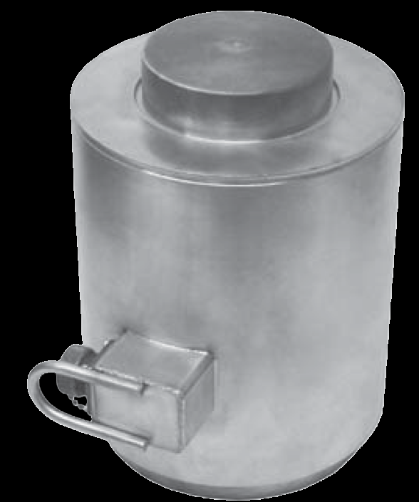
WIKA Sensor Technology canister load cells are tall, cylindrical cells built for high capacity and harsh service — environmentally sealed stainless bodies that carry columnar compression to 750,000 lb. The sealed construction suits subsea, offshore, and outdoor load monitoring where moisture would drift an unsealed bridge, as well as large tank, silo, and vessel weighing. These are the WIKA-ST (legacy tecsis XLUG / XLCC) cells — send a tecsis part number and we cross-reference the current WIKA-ST equivalent.
Key Features & Benefits
- Proven strain-gauge measurement — a bonded-foil Wheatstone bridge reads the deflection of an elastic metal element — the measurement principle that has anchored electrical force measurement for decades. A repeatable, well-understood physics, not a novelty.
- All-stainless, sealed for the plant floor — welded stainless bodies keep moisture and contaminants out of the bridge — the leading cause of load-cell drift — so the cell holds calibration in industrial service. Built to survive where it is installed.
- Reads into what you already have — a low-level mV/V bridge output feeds any indicator or DAQ with bridge conditioning; an inline amplifier is available where a 4–20 mA or voltage signal has to run to a PLC. Match the output to the receiver, not the other way around.
- A form factor for how the load arrives — pancake, S-type, canister, rod-end, bending-beam, and subminiature builds let you introduce the load the way the application allows — axially, in-line, hanging, or in a tight pocket. The element shape is chosen for the load path.
- Legacy tecsis part numbers cross-referenced — these XL-series cells are the tecsis line, now built and shipped under WIKA Sensor Technology; a legacy tecsis part number cross-references to its current WIKA-ST equivalent. An installed-base part number is still a live order.
Specifications
- Operating principle
- A bonded-foil strain-gauge bridge measures axial strain in a tall, stiff cylindrical (canister) element. The high, columnar stiffness gives excellent repeatability at high capacity, the reason canister cells anchor high-capacity weighing and force standards.
- Force mode
- XLUG tension and compression; XLCC compression only.
- Form factor & mounting
- Cylindrical canister body with a threaded load point on both ends (XLUG); the load introduces axially. For high-capacity weighing, process, and reference / calibration use.
- Body / element material
- Stainless steel casing.
- Construction & sealing
- Robust, environmentally sealed stainless construction; ASTM E74 reference-class calibration is available.
- Capacity / measuring range
- XLUG 0–100 to 0–200,000 lb; XLCC 0–10,000 to 0–750,000 lb.
- Output
- XLUG 3 mV/V ±0.25%; XLCC 2 mV/V (3.0 mV/V optional).
- Excitation
- 10 VDC.
- Bridge resistance
- 350 Ohms.
- Non-linearity
- ±0.03% FSO (XLUG ±0.05% FSO for capacities under 250 lb and over 75,000 lb).
- Hysteresis
- ±0.03% FSO (XLUG ±0.05% FSO for capacities under 250 lb and over 75,000 lb).
- Repeatability
- XLUG 0.02% FSO; XLCC ±0.01% FSO.
- Zero balance
- ±1% FSO.
- Operating temperature range
- XLUG +30 to +185°F (−1 to +85°C); XLCC −30 to +185°F (−34 to +85°C).
- Compensated temperature range
- +60 to +160°F (+15 to +71°C).
- Thermal effects (zero / span)
- On zero ±0.0015% FSO/°F; on span ±0.0008% reading/°F.
- Overload (safe / ultimate)
- Safe overload 150% of capacity.
- Electrical connection
- MS3102E-14S-6P connector (or equal); integral cable optional.
- Calibration
- Standard calibration positive in tension (XLUG); ASTM E74 reference calibration and calibration-class selection available.
- Options
- Dual bridge; ASTM E74 calibration; bridge resistance; integral cable; metric threads.
- Lead time & quotation
- Quote-only, no public price list; lead time runs with capacity, calibration class, and dual-bridge redundancy. Use the input form to send a legacy tecsis part number for a current WIKA-ST cross-reference.
Common Applications
- High-capacity tank, silo, and vessel weighing — to 750,000 lb (~375 short tons)
- Truck, rail, and platform scales (multi-cell arrays)
- Subsea and offshore load monitoring — environmentally sealed stainless
- Structural and civil columnar load monitoring
- Reference and calibration force standards (ASTM E74 class available)
Design & Selection Considerations
- Size the capacity to land the working load in the upper-middle of the range — aim for the routine load at roughly 50–90% of capacity: enough resolution and signal-to-noise, with headroom so peaks and transients never exceed the rating. Oversize and resolution suffers; undersize and an overload shifts the calibration. Account for shock and dynamic peaks, not just the static load.
- Keep the load axial, centered, and free of side load — most cells are rated for axial force only — an off-center or side load reads wrong and can damage the cell. Use the manufacturer’s load buttons / rod ends, keep the structure stiff and aligned, and on multi-cell arrays mount every cell coplanar. Most load-cell errors in the field are installation errors, not sensor errors.
- Read the accuracy terms the same way on every datasheet you compare — FSO quotes the error against full range, so a %FSO figure is a larger relative error at low load; BFSL reports linearity against a best-fit line. A ±0.03% cell is test-and-measurement grade, ±0.25–1% is industrial / OEM grade. Make sure two cells quote accuracy the same way before you compare them.
- Pick the output from what receives the signal and how far away it is — a raw mV/V bridge is right into a DAQ or indicator with bridge conditioning on a short, shielded run; an inline amplifier (4–20 mA or voltage) reads straight into a PLC and rides out long, noisy cable runs. Decide it from the receiver, not by default.
- Overload past safe but short of burst is the dangerous zone — safe overload (commonly 150% of capacity) is the load the cell can see without losing calibration; the ultimate rating is where it is destroyed. A cell overloaded between the two keeps reporting plausible, wrong numbers. Recalibrate after any suspected overload before you trust the data.
- Match the body material and temperature range to the environment — aluminum bodies are lighter and lower-cost; stainless resists corrosion and washdown; every cell has a compensated temperature band, with extended-temperature compensation available where the process runs hot or cold. Specify the environment up front and the material and compensation get built in.
To spec the right WIKA-ST canister load cell:
Use the input form to tell us the capacity (and the real worst-case peak), the force mode (tension, compression, or both), the accuracy class you need, how the load is introduced and how much room there is, the output (mV/V or amplified 4–20 mA / voltage) and the receiving device, the environment (temperature, washdown, hazardous area), and any calibration documentation or approval required (ASTM E74, OIML / NTEP). A legacy tecsis part number is enough to start — we cross-reference the current WIKA-ST equivalent.
Force & Pressure Application Sheet ›Talk to an engineer directly — Scott Prater, Principal · 917-580-0878 · scott@pratertechnical.com
Specifications compiled by Prater Technical Partners from WIKA product datasheets.