Product Overview
A dynamic / high-frequency pressure transducer is built for fast events — water hammer, valve and actuator slam, pipeline surge, seal burst, and combustion or gun-chamber pressure — that an ordinary process transmitter is too slow to capture before the peak is gone. The WIKA-ST flagship is the XPMD DynAstat, which responds from DC to 100 kHz, with a sensing element whose natural frequency runs from about 35 kHz up to 162 kHz depending on range. The rule for a dynamic measurement: the transducer’s natural frequency must sit well above the frequency content of the event, or the reading is distorted by the sensor’s own resonance — so tell us the rise time or frequency of the transient and we size the natural frequency around it. Have a legacy tecsis part number for this measurement? Send it — WIKA acquired tecsis and now ships these under WIKA Sensor Technology, and we cross-reference the tecsis p/n to the current WIKA-ST equivalent at the same spec.
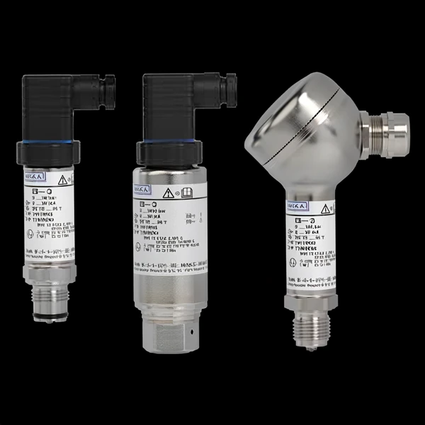
Key Features & Benefits
- Captures the peak an ordinary transmitter misses — a process transmitter’s mechanical and electrical response is too slow for a fast event, so it never sees the real peak; a high-natural-frequency dynamic transducer responds fast enough to record the transient as it happens. The difference between logging the spike and logging a smeared average of it.
- Dynamic and static on one element — the DynAstat measures both the steady pressure and the fast transient riding on it, so you can watch a surge against its baseline without a second sensor. Baseline and burst from the same instrument.
- Natural frequency sized to your event — the sensing element is offered across a band of natural frequencies, so the unit can be matched to the rise time or frequency content of the specific transient you are chasing. Sized to your event, so the reading is the pressure and not the sensor ringing.
- Insensitive to installation torque — the reading barely shifts with how hard the transducer is torqued into its port, so a field install repeats the calibration instead of offsetting it — one less variable on a sensor that is already chasing a fast, hard-to-repeat event. Tighten it to seal, not to a torque-spec sheet.
Specifications
- Sensing principle
- High-frequency strain-gauge pressure sensing on an element with a high natural frequency — the XPMD DynAstat measures both dynamic and static pressure and is very insensitive to installation torque, so it captures a peak before it is gone where an ordinary process transmitter is too slow to respond.
- Pressure type
- Dynamic and static pressure, gauge reference (psig) — a fast transient riding on its baseline (water hammer, valve and actuator slam, pipeline surge, seal burst, combustion and gun-chamber pressure).
- Measuring range
- 0–500 to 0–10,000 psig, in six capacities — 500 / 1,000 / 2,500 / 5,000 / 7,500 / 10,000 psi (part numbers 99-5936-0500 through 99-5936-010K).
- Accuracy
- Linearity ±0.25% FSO; hysteresis ±0.1% FSO; repeatability ±0.1% FSO; torque sensitivity ±0.05% FSO.
- Thermal effects
- Zero ±0.01% FSO/°F; span ±0.02% reading/°F.
- Output signal
- 3 mV/V analog — a single output from DC to 100 kHz.
- Excitation / supply
- 10 VDC.
- Electrical connection
- Bendix PTIH-10-6P connector or equal (differential ±input / ±output).
- Frequency response
- DC to 100 kHz; the sensing element’s natural frequency runs from ≥35 kHz (500 psi) up to ≥162 kHz (10,000 psi) — for an undistorted reading it must sit well above the frequency content of the event. See the per-range table below.
XPMD DynAstat — capacity, natural frequency & frequency response
| Capacity (psig) | Part number | Natural frequency | Frequency response |
|---|---|---|---|
| 500 | 99-5936-0500 | ≥35 kHz | 23 kHz |
| 1,000 | 99-5936-001K | ≥50 kHz | 33 kHz |
| 2,500 | 99-5936-02K5 | ≥82 kHz | 55 kHz |
| 5,000 | 99-5936-005K | ≥121 kHz | 100 kHz |
| 7,500 | 99-5936-07K5 | ≥146 kHz | 100 kHz |
| 10,000 | 99-5936-010K | ≥162 kHz | 100 kHz |
- Wetted parts material
- 17-4 PH stainless steel.
- Process connection
- 7/16-20 UNF, O-ring groove (supplied with a 012 O-ring).
- Overpressure / proof
- Safe overload 150% of capacity.
- Operating temperature
- −65 to +250°F (−54 to +121°C).
- Compensated temperature
- −40 to +140°F (−40 to +60°C).
- Configuration & lead time
- Configured to the rise time / frequency of the transient so the natural frequency is sized above it; options include an extended compensated temperature range and various electrical and pressure connections. Specialty high-frequency unit — longer lead than the general-industrial lines. Quote-only, no public price list.
Common Applications
- Water hammer and hydraulic transient capture in piping
- Valve and actuator slam — fast-closure pressure spikes
- Pipeline surge and pressure-wave propagation
- Pump and compressor pulsation and cavitation monitoring
- Internal-combustion engine cylinder and gas-turbine combustion pressure
- Gun-chamber, ballistics, and blast / detonation pressure
- Fuel-injection and common-rail pressure dynamics
- Seal, hose, and component burst testing
- Shock-tube, blast, and explosion research
- Rocket and propulsion test-stand pressure transients
- R&D and test-stand transient pressure characterization
Design & Selection Considerations
- Natural frequency must beat the event — or the sensor rings — a useful rule of thumb is to keep the sensor’s natural frequency at least five to ten times the highest frequency in the transient; closer than that and the element begins to resonate, so the record shows the sensor’s own ringing superimposed on — or in place of — the real pressure. When in doubt, oversize the natural frequency and filter in post. A slow sensor on a fast event does not just lag — it lies.
- Mounting and dead volume change what you measure — on a fast event the plumbing matters as much as the sensor: a recessed port, a long passage, or a trapped gas pocket adds its own delay and resonance ahead of the diaphragm. Mount the transducer flush and close to the event. The fastest sensor in the world reads slow through a long snubber tube.
- Respect the overpressure limit — the danger zone is below burst — proof / safe-overpressure is the pressure the sensor can see without losing calibration; burst is where it is destroyed. A burst or combustion event that drives the unit past proof but short of burst leaves it reporting plausible, wrong numbers. Recalibrate after any suspected overpressure. A spike that shifts calibration leaves no visible mark.
To spec the right WIKA-ST dynamic pressure transducer:
To size and select the right transducer, send us: the pressure range and whether it is gauge, absolute, sealed, or differential; for a differential measurement, the maximum line (static) pressure as well as the differential range; the accuracy class you need (standard industrial vs. high-accuracy); the output the receiving device expects (4–20 mA, 0–5 V, 0–10 V, or raw mV/V) and the cable run; the process medium and temperature (so the wetted material and any extended temperature compensation are right); the process connection and electrical termination; and any area classification or agency approval (Ex / intrinsic safety, CSA, FM) and NACE / sour-service material requirement. For a fast transient, give us the rise time or frequency of the event so the natural frequency is sized above it.
Force & Pressure Application Sheet ›Talk to an engineer directly — Scott Prater, Principal · 917-580-0878 · scott@pratertechnical.com
Specifications compiled by Prater Technical Partners from WIKA product datasheets.