Product Overview
The Activa and Ultima are Flo-tech’s compact sensor arrays — one small turbine body, built for OEM and test-stand integration, that returns flow with optional pressure and temperature from a single hydraulic line break. They are the same array split by output stage: the Activa has the IFC (Intelligent Frequency Converter) built in, converting the flow frequency to 4–20 mA or 0–5 VDC at 1:4000 resolution and reading ±1% of reading; the Ultima sends the magnetic pick-up’s raw frequency native to the F6600/F6650 displays, reading ±1% of full scale. Both repeat to ±0.2%, respond in under 200 ms, handle four flow ranges from 0.4 to 160 GPM (1.5 to 605 LPM) on SAE or BSPP ports, work to 5800 PSI and +300°F, and feed a PC, PLC, recorder, or Flo-tech panel display. Order the body to suit what reads the signal — analog host or frequency counter — and add the pressure and temperature sensors per the stand.
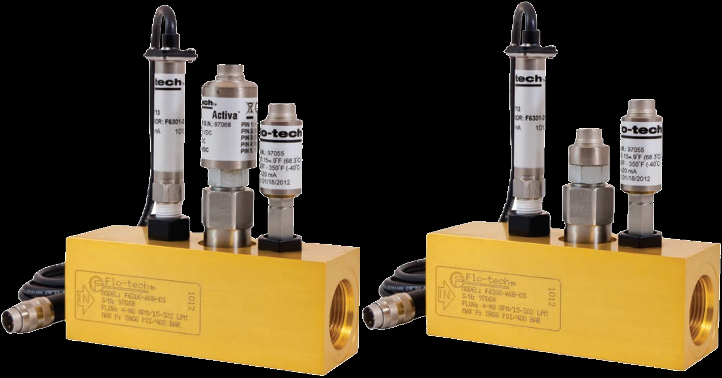
One array body, two output stages
The Activa and Ultima are the same compact turbine array — same body, same flow ranges, ports, materials, ±0.2% repeatability, sub-200 ms response, and the same optional pressure and temperature sensors. They differ only in how the flow signal leaves the meter, which sets the accuracy basis and the matching display.
- Built-in IFC (Intelligent Frequency Converter) outputs 4–20 mA or 0–5 VDC for flow rate at 1:4000 resolution
- Flow accuracy ±1% of reading @ 32 cSt
- Drives any analog host (PC, PLC, recorder) or the F6700/F6750 displays
Key Features & Benefits
- One line break, three readings — the compact array packs a turbine rotor, an optional pressure tap, and a temperature probe into one housing, so a single port into the circuit returns all three readings at once — one line break instead of three instruments. Built to drop into a test stand or machine.
- Pick the output stage for the host — the Activa carries a built-in IFC that puts out an analog flow signal (4–20 mA or 0–5 VDC, 1:4000 resolution) at ±1% of reading; the Ultima sends the raw turbine pulse for a frequency counter or a matching display. Same body, two output paths.
- Integrates straight into stands and controls — each signal drops into a PC, PLC, recorder, or panel display, which is what makes these the arrays for test stands, stationary system monitoring, feedback for hydraulic control, and impending-failure warning. Wire it to the instrument you already run.
- Turbine that tolerates the duty — no gauge to read, no moving linkage to wear — an anodized-aluminum body with a stainless rotor, ±0.2% repeatability, and a sub-200 ms response handles the shock and cycling of stand and machine service. Compact enough to mount inline and forget.
Specifications
- Measurement principle
- Turbine — fluid spins a bladed rotor at a speed proportional to flow rate; a magnetic pick-up senses the blades and generates a frequency. The compact body packs the rotor with an optional pressure tap and temperature probe, so one line break reads flow, pressure, and temperature at the same point. The Activa adds a built-in IFC (Intelligent Frequency Converter) that turns the frequency into an analog output; the Ultima outputs the raw frequency (see Variants).
- Measured parameters
- Flow, plus pressure and temperature when the optional pressure and temperature sensors are fitted — all from one hydraulic line break.
- Flow ranges
- Four ranges per body: 0.4–7, 1–40, 4–80, and 8–160 GPM on SAE 8/12/16/20; 1.5–26, 3.8–151, 15–302, and 30–605 LPM on G 1/4 to G 1-1/4.
- Accuracy
- Activa ±1% of reading @ 32 cSt (the IFC output); Ultima ±1% of full scale (±1% of rate when read on an F6600/F6650 display) — the output stage sets the accuracy basis (see Variants).
- Repeatability
- ±0.2%.
- Turbine response time
- ≤200 ms turbine response.
- Calibration reference fluid
- Calibrated on 0.876 SG / 150 SUS (32 cSt) hydraulic oil, irrespective of the final fluid in use.
- Functional viscosity range
- Functional range roughly 25 to 500 SUS (2 to 110 cSt).
- Operating / fluid temperature
- Fluid −4 to +300°F (−20 to +150°C); ambient −4 to +131°F (−20 to +55°C). A fitted pressure sensor narrows the fluid range to that device’s rating.
- Maximum pressure
- Up to 5800 PSI (400 Bar).
- Port / connection sizes
- SAE 8, 12, 16, 20 (J1926/1) or G 1/4, 3/4, 1, 1-1/4 BSPP (ISO 1179).
- Body / housing materials
- Anodized 6013-T651 aluminum housing; T416 stainless rotor, 440C stainless ball bearings, T303 stainless rotor shaft.
- Wetted materials
- Anodized aluminum housing and adapters, T416 stainless rotor, 6061-T6 aluminum (or CA360 brass on the smallest bodies) rotor supports and hub cones, T303 stainless pick-up. Seals: Buna-N standard; Viton® or EPR optional.
- Outputs
- Activa: IFC 4–20 mA or 0–5 VDC for flow rate at 1:4000 resolution. Ultima: raw magnetic-pickup frequency for flow rate. On both, the optional pressure and temperature sensors add their own 4–20 mA outputs (see Variants).
- Display
- No on-board display — the signals drive a PC, PLC, recorder, or a Flo-tech panel display: Activa to the F6700/F6750, Ultima flow to the F6600/F6650 with pressure and temperature to the F6700/F6750.
- Calibration certificate
- Three points of calibration data ship with every sensor; an optional NIST-traceable 5-point or 10-point certificate is available at order.
Common Applications
- Fluid-characteristic measurement on hydraulic test stands
- Stationary hydraulic-system monitoring built into a machine or skid
- Feedback for hydraulic-system control loops
- Advance warning of impending component failure on continuously monitored circuits
- Mobile hydraulic-system diagnosis where a compact inline array fits the package
Design & Selection Considerations
- Activa vs Ultima is an output decision, not an accuracy upgrade — both are the same turbine array; the Activa’s IFC reads ±1% of reading and the Ultima reads ±1% of full scale, so the gap only matters at the bottom of the range. Choose the Activa for an analog host and the tighter reading-based figure; choose the Ultima when a frequency counter or an F6600/F6650 display already does the math. Use the input form to tell us what reads the signal and we set the right body.
- Pressure and temperature are options, not standard — the array meters flow on its own; the silicon-strain pressure sensor (4–20 mA, ratings to 6000 PSI) and the platinum-RTD temperature sensor (4–20 mA, to +350°F) are ordered per port. A fitted pressure sensor also caps the fluid temperature to that device’s rating. Specify which parameters the stand needs so the right plugs and sensors are configured.
- Viscosity sets where the reading holds — like any turbine the calibration is referenced to 0.876 SG / 150 SUS (32 cSt) oil, with a functional range of about 25 to 500 SUS (2 to 110 cSt). For work far from 32 cSt, tell us the operating viscosity so we confirm it sits in range and set the right accuracy expectation. When the reading has to be traceable, order the array with a NIST-traceable 5-point or 10-point certificate.
To configure the right Activa or Ultima array:
Use the input form to tell us the hydraulic circuit, the flow range and port size, the working pressure and temperature, the fluid and its operating viscosity, and what you need the reading to do — a live field check, recorded data, or a permanent stand — and we’ll match the tester, sensor, and display, confirm the output and any NIST-traceable calibration, and price it — with programming and commissioning available as an optional, quoted service.
Flow Meter Application Sheet ›Talk to an engineer directly — Scott Prater, Principal · 917-580-0878 · scott@pratertechnical.com
Specifications compiled by Prater Technical Partners from Badger Meter Flo-tech hydraulic test & diagnostics product literature.