Product Overview
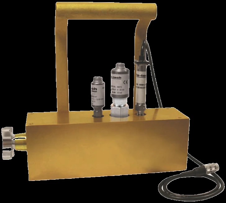
The F6100 is Flo-tech’s fixed-mount sensor array, reading flow, pressure, and temperature from one set of line connections and adding an integral fingertip load valve that restricts the circuit on demand — so the same fixture both takes the reading and applies the back-pressure the test needs. Plumbed permanently into a bench or a machine, it is the instrument for recurring hydraulic work: dialing in a relief-valve setting, watching flow fall off to find a leaking valve or cylinder, or holding a pump or motor at rated pressure to baseline its efficiency — without breaking back into the circuit each time. Four flow ranges reach 199.9 GPM across SAE and BSPP ports, with the body rated to 6,000 psi and +300°F. The flow signal leaves as a raw frequency pulse or, via the on-board IFC, as a 4–20 mA or 0–5 VDC analog line; flow reads ±1% of reading at 32 cSt and repeats to ±0.2%. Pressure and temperature transducers are ordered options, each adding a 4–20 mA loop, and a factory NIST-traceable certificate is available.
Key Features & Benefits
- Measures and loads at one station — flow, pressure, and temperature come off one tee in the line, and the fingertip loading valve restricts that same circuit — so a relief-valve setting, a leak check on a worn valve or cylinder, or a pump or motor held at rated pressure all run on a single instrument rather than a bench of separate gear. One fixture does the test and the load.
- Built into the stand, not carried to it — unlike the hand-carried PFM6, the F6100 plumbs permanently into a test bench or a machine, so a recurring check — line acceptance, end-of-line QC, a PM trend — runs the same way every time without breaking into the circuit. Wire it once; test on demand.
- Output to match your readout — specify a raw frequency pulse for a Flo-tech panel display or a counter you already run, or the on-board IFC to convert that pulse to an analog 4–20 mA or 0–5 VDC line for the controller; and any fitted pressure or temperature sensor brings its own 4–20 mA loop. Land the data where the stand needs it.
- Rated for high-pressure hydraulics — operating pressure runs to 6,000 psi with a 7,500 psi relief disc and surge protection on the load valve, across four flow ranges to 199.9 GPM in SAE or BSPP ports. Sized for real test-stand duty.
Specifications
- Measurement principle
- Turbine, with an integrated load valve — the passing fluid spins a bladed rotor at a speed proportional to flow; a pressure tap and a temperature probe read the same point, so one array reports flow, pressure, and temperature together. A fingertip loading valve throttles the circuit to set a back-pressure on demand — the array both measures and loads.
- Measured parameters
- Flow, pressure, and temperature at one connection, with the load valve setting the test pressure.
- Flow ranges
- Four ranges — 1–15, 2–30, 4–85, and 7–199.9 GPM (4–56, 7.5–113.6, 15–321, and 26–757 LPM), by port size.
- Accuracy
- Flow ±1% of reading at 32 cSt, the calibration viscosity — whether the flow signal is taken as frequency (magnetic pickup) or through the on-board IFC. The optional pressure sensor is ±1% of full scale.
- Repeatability
- ±0.2%.
- Calibration reference fluid
- 0.876 SG / 150 SUS (32 cSt) hydraulic oil, irrespective of final fluid use.
- Functional viscosity range
- Functional over roughly 25 to 500 SUS (2 to 110 cSt).
- Operating / fluid temperature
- Fluid −4 to +300°F (−20 to +150°C); ambient −4 to +131°F (−20 to +55°C).
- Maximum pressure
- Operating pressure to 6,000 psi (414 bar). A 7,500 psi pressure-relief disc is fitted.
- Port / connection sizes
- SAE 12, SAE 16, and SAE 24 straight-thread O-ring boss (J1926/1), or G 3/4, G 1, and G 1-1/2 BSPP (ISO 1179), by range.
- Body / housing materials
- Anodized 6013-T651 aluminum housing with a cast anodized-aluminum carrying handle; the loading-valve body is plated steel.
- Wetted materials
- T416 stainless turbine rotor, 440C stainless ball bearings, T303 stainless rotor shaft, valve stem, and temperature probe; seals are Buna N standard, with Viton® or EPR optional.
- Outputs
- Order the flow signal as frequency (magnetic pickup, 0–3500 Hz), 4–20 mA, or 0–5 VDC (the last two via the on-board IFC, 1:4000 resolution). The optional pressure and temperature sensors each output 4–20 mA.
- Power
- IFC is loop-powered, 10–30 VDC supply.
- Calibration certificate
- Optional factory 5-point or 10-point calibration certificate, NIST-traceable (ISO 9001).
Common Applications
- Permanent hydraulic test stands — pump, motor, valve, and cylinder acceptance and end-of-line QC
- Setting and verifying relief-valve and pressure-control settings under load
- Finding internal leakage in a valve or cylinder by loading the circuit and watching flow fall off
- Pump and motor efficiency baselining against factory specifications
- Hydrostatic-drive and machine-mounted diagnostic monitoring built into the equipment
Design & Selection Considerations
- Pick the output for the readout it feeds — the F6100 ships as a frequency (magnetic-pickup) array or with the on-board IFC. Frequency feeds a Flo-tech display or your own counter; the IFC gives a 4–20 mA or 0–5 VDC signal into a PLC or data system, at 1:4000 resolution. Flow accuracy is ±1% of reading at 32 cSt either way — the choice is about how the reading has to land, not how tight it is. Decide that before you fix the output.
- Size the body to the flow, not the line — the four ranges overlap, and a turbine reads best in the upper part of its band. Use the input form to tell us the working flow and the lowest rate you need to resolve, and we set the range and port (SAE or BSPP) so the rotor sits in its accurate window rather than loafing at the bottom of an oversized body.
- Calibration is on 32 cSt oil — confirm the operating viscosity — the array is calibrated on 0.876 SG / 150 SUS (32 cSt) hydraulic oil, functional over about 2 to 110 cSt. Like any turbine, the reading shifts as the fluid thickens, so for work far from 32 cSt tell us the operating viscosity and we confirm it sits in range and set the accuracy expectation. When the number has to be traceable, order the 5-point or 10-point NIST certificate.
- The pressure and temperature sensors are options — the load valve and turbine flow path are the core array; the silicon strain-gauge pressure sensor and the platinum-RTD temperature sensor (each 4–20 mA) are ordered options. Specify the pressure rating and whether you need temperature so the array is built complete for the test.
To size & select the right F6100 sensor array:
Use the input form to tell us the test-stand or machine the array mounts in, the working flow range and port (SAE or BSPP), the pressure and temperature you need to load and read, the fluid and its operating viscosity, and how the signal has to land — a frequency pulse to a display, or 4–20 mA / 0–5 VDC to a PLC — and we’ll set the range, output, the pressure and temperature options, and any NIST-traceable calibration, and price it — with programming and commissioning available as an optional, quoted service.
Flow Meter Application Sheet ›Talk to an engineer directly — Scott Prater, Principal · 917-580-0878 · scott@pratertechnical.com
Specifications compiled by Prater Technical Partners from Badger Meter Flo-tech hydraulic test & diagnostics product literature.