Product Overview
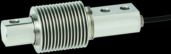
The WIKA-ST F3203 is a hermetically sealed OIML bending beam: a stainless weighing element with the strain bridge welded inside a bellows to IP68/IP69K, reading 0–20 to 0–500 kg at a precision-class 0.017% Fnom linearity. It is certified to OIML R60 Class C (3,000 intervals) for legal-for-trade service, which makes it the element under hopper, dosing, price-labelling, and industrial platform scales — especially the ones that get washed down. Use the input form to send a legacy tecsis part number and we cross-reference the current WIKA-ST equivalent.
Key Features & Benefits
- Hermetic where a weighing element usually fails — the welded stainless bellows seals the gauge to IP68/IP69K, so washdown, condensation, and hose-down cleaning cannot drift the bridge — the leading cause of dead weighing elements in wet plants. The beam for the floor that gets hosed.
- Legal-for-trade out of the box — OIML R60 Class C certification at 3,000 intervals means the same cell that runs the process can run the certified transaction — price labelling, trade weighing, dosing to declared weight. One element for process and commerce.
- Precision-class numbers on a workhorse form — 0.017% Fnom linearity with ±0.015% reversibility puts this bending beam in precision-scale territory while it mounts like any platform element. Accuracy that does not need a lab around it.
- Mounting kit, not machining — AZK stainless mounting kits, base plates, and load feet drop the beam into a hopper leg or platform frame without custom hardware. The install is a catalog line, not a fabrication job.
Specifications
- Operating principle
- A bonded-foil strain-gauge bridge reads the bending strain in a stainless beam element sealed inside a hermetically welded bellows — the weighing element for hopper, platform, and dosing scales that get washed down.
- Force mode
- Static and dynamic weighing; the load is introduced vertically through the centre of the beam, free of transverse force.
- Form factor & mounting
- Beam fixed at one end with the load introduced at the free end; 120 mm body mounted on a flat surface (tangential and radial mounting arrangements shown on the sheet).
- Body / element material
- Stainless steel.
- Construction & sealing
- Hermetically sealed, welded stainless bellows — ingress protection IP68 and IP69K.
- Capacity / measuring range
- 0–20 to 0–500 kg (20, 50, 100, 200, 500 kg).
- Output
- 2.0 mV/V (±0.1% for 50–500 kg; ±0.2% at 20 kg).
- Excitation
- DC 10–15 V.
- Bridge resistance
- Input 400 ± 20 Ohms; output 350 ± 3 Ohms; insulation resistance ≥5,000 MOhms.
- Non-linearity
- 0.017% Fnom — precision class.
- Hysteresis
- Reversibility ±0.015% Fnom; creep over 30 min <±0.016% Fnom.
- Operating temperature range
- −22 to +158°F (−30 to +70°C).
- Compensated temperature range
- Rated (nominal) +14 to +104°F (−10 to +40°C).
- Thermal effects (zero / span)
- On zero ≤±0.02%/10 K; on characteristic value ≤±0.012%/10 K.
- Overload (safe / ultimate)
- Force limit (safe) 150% Fnom; breaking force 200% Fnom.
- Electrical connection
- Integral measuring cable Ø4 mm × 3 m (PVC).
- Options
- Certified to OIML R60 Class C (3,000 intervals) for legal-for-trade weighing; AZK01 / AZK03 stainless mounting kits, base plates, load feet, and rubber elements; a junction box handles signal trimming in multi-cell arrays.
- Lead time & quotation
- Quote-only, no public price list; lead time runs with capacity, approval, and mounting accessories. Use the input form to send a legacy tecsis part number for a current WIKA-ST cross-reference.
Common Applications
- Hopper scales and industrial scales
- Price-labelling scales — legal-for-trade (OIML R60 Class C)
- Dosing units and batching weight control
- Laboratory and process technology weighing
- Washdown and wet-area platforms where sealing decides the service life
Design & Selection Considerations
- Trim multi-cell arrays at the junction box — a platform or hopper on several beams reads the sum of slightly unequal cells; the junction box carries the trimming that equalizes corner outputs. Budget it into the install rather than chasing corner error in the indicator. Corner trim is hardware, not calibration.
- Size the capacity to land the working load in the upper-middle of the range — aim for the routine load at roughly 50–90% of capacity: enough resolution and signal-to-noise, with headroom so peaks and transients never exceed the rating. Oversize and resolution suffers; undersize and an overload shifts the calibration. Account for shock and dynamic peaks, not just the static load.
- Keep the load axial, centered, and free of side load — most cells are rated for axial force only — an off-center or side load reads wrong and can damage the cell. Use the manufacturer’s load buttons / rod ends, keep the structure stiff and aligned, and on multi-cell arrays mount every cell coplanar. Most load-cell errors in the field are installation errors, not sensor errors.
- Read the accuracy terms the same way on every datasheet you compare — FSO quotes the error against full range, so a %FSO figure is a larger relative error at low load; BFSL reports linearity against a best-fit line. A ±0.03% cell is test-and-measurement grade, ±0.25–1% is industrial / OEM grade. Make sure two cells quote accuracy the same way before you compare them.
- Pick the output from what receives the signal and how far away it is — a raw mV/V bridge is right into a DAQ or indicator with bridge conditioning on a short, shielded run; an inline amplifier (4–20 mA or voltage) reads straight into a PLC and rides out long, noisy cable runs. Decide it from the receiver, not by default.
- Overload past safe but short of burst is the dangerous zone — safe overload (commonly 150% of capacity) is the load the cell can see without losing calibration; the ultimate rating is where it is destroyed. A cell overloaded between the two keeps reporting plausible, wrong numbers. Recalibrate after any suspected overload before you trust the data.
- Match the body material and temperature range to the environment — aluminum bodies are lighter and lower-cost; stainless resists corrosion and washdown; every cell has a compensated temperature band, with extended-temperature compensation available where the process runs hot or cold. Specify the environment up front and the material and compensation get built in.
To spec the right WIKA-ST bending-beam load cell:
Use the input form to tell us the capacity (and the real worst-case peak), the force mode (tension, compression, or both), the accuracy class you need, how the load is introduced and how much room there is, the output (mV/V or amplified 4–20 mA / voltage) and the receiving device, the environment (temperature, washdown, hazardous area), and any calibration documentation or approval required (ASTM E74, OIML / NTEP). A legacy tecsis part number is enough to start — we cross-reference the current WIKA-ST equivalent.
Force & Pressure Application Sheet ›Talk to an engineer directly — Scott Prater, Principal · 917-580-0878 · scott@pratertechnical.com
Specifications compiled by Prater Technical Partners from WIKA product datasheets.