Product Overview
The tecsis XLA parallelogram load cell (now WIKA Sensor Technology) is an OEM component: a 1.74-inch parallelogram flexure measuring 2.2 to 500 lb with a built-in overload stop, designed to disappear inside a weighing or force-sensing product. The double-beam geometry keeps deflection parallel, the gauge reads ±0.02% FSO on the small ranges, and the body is aluminum through 100 lb and 17-4 PH stainless above — a catalog part an OEM designs around rather than a finished instrument. Use the input form to send a tecsis part number and we cross-reference the current WIKA-ST equivalent.
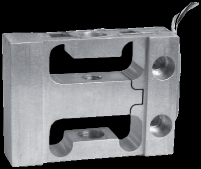
Key Features & Benefits
- The overload stop is machined in — the flexure bottoms on its own body before the gauge over-strains — on the small ranges a 2.2-lb cell survives 250 lb — so a jam, a drop, or a careless hand does not kill the sensor inside your product. Overload protection that ships in every unit, not as an option.
- Designed to be built in, not bolted on — a 1.74-inch, 1–3-oz block with standard thread patterns and 12-inch leads — the package is the OEM integration, sized for the mechanism it disappears into. A component, not an instrument.
- Ounce-class resolution with %-of-a-percent behavior — ranges start at 2.2 lb with ±0.02% FSO linearity, hysteresis, and repeatability — precision-scale numbers at capacities where most industrial cells have not started reading yet. Small forces measured honestly.
Specifications
- Operating principle
- A parallelogram flexure with a bonded strain-gauge bridge — the double-beam geometry that keeps the measuring surface parallel as it deflects, in a package designed for building INTO an OEM product rather than bolting under a platform.
- Force mode
- Compression (standard calibration positive in compression).
- Form factor & mounting
- 1.74″ body, 1–3 oz — a machined block with mounting threads 10-32 UNF (2.2–200 lb) or 1/4-28 UNF (500 lb); nominal deflection 0.002–0.007″ by range.
- Body / element material
- Aluminum (100 lb and below); 17-4 PH stainless (200 lb and above).
- Construction & sealing
- Machined flexure with a built-in overload stop — the travel limit is part of the body, not an accessory.
- Capacity / measuring range
- 0–2.2 to 0–500 lb (2.2, 5, 10, 25, 50, 100, 200, 500 lb).
- Output
- 2 mV/V nominal.
- Excitation
- 10 V AC-DC (18 V max).
- Bridge resistance
- 1,000 Ohms.
- Non-linearity
- ±0.02% FSO (100 lb and below); ±0.06% FSO (200 lb and above).
- Hysteresis
- ±0.02% FSO (≤100 lb); ±0.06% FSO (≥200 lb).
- Repeatability
- ±0.02% FSO.
- Zero balance
- ±3.0% FSO.
- Operating temperature range
- −60 to +200°F.
- Compensated temperature range
- +60 to +160°F.
- Thermal effects (zero / span)
- On zero ±0.005% FSO/°F; on span ±0.005% reading/°F.
- Overload (safe / ultimate)
- Built-in overload stop: protection to 250 lb on the 100-lb-and-below cells; 200% of capacity on 200 lb and above.
- Electrical connection
- 4 lead wires, 12″ long.
- Options
- Alternative bridge resistance; inline amplifier.
- Lead time & quotation
- Quote-only, no public price list; OEM quantities quoted with the design. Use the input form to send a legacy tecsis part number for a current WIKA-ST cross-reference.
Common Applications
- OEM weighing mechanisms — the cell is designed into the product
- Industrial weighing applications in the cantilever/parallelogram family
- Benchtop instruments and dispensing heads measuring ounce-to-pound forces
- Compact automation force feedback where overload abuse is expected
Design & Selection Considerations
- Design to the deflection, not just the capacity — the flexure moves 0.002–0.007″ at rated load and its overload stop works by bottoming that travel — the mechanism around it must allow the motion and must not re-route force past the cell. In an OEM assembly, the load path is part of your design, not ours.
- Size the capacity to land the working load in the upper-middle of the range — aim for the routine load at roughly 50–90% of capacity: enough resolution and signal-to-noise, with headroom so peaks and transients never exceed the rating. Oversize and resolution suffers; undersize and an overload shifts the calibration. Account for shock and dynamic peaks, not just the static load.
- Keep the load axial, centered, and free of side load — most cells are rated for axial force only — an off-center or side load reads wrong and can damage the cell. Use the manufacturer’s load buttons / rod ends, keep the structure stiff and aligned, and on multi-cell arrays mount every cell coplanar. Most load-cell errors in the field are installation errors, not sensor errors.
- Read the accuracy terms the same way on every datasheet you compare — FSO quotes the error against full range, so a %FSO figure is a larger relative error at low load; BFSL reports linearity against a best-fit line. A ±0.03% cell is test-and-measurement grade, ±0.25–1% is industrial / OEM grade. Make sure two cells quote accuracy the same way before you compare them.
- Pick the output from what receives the signal and how far away it is — a raw mV/V bridge is right into a DAQ or indicator with bridge conditioning on a short, shielded run; an inline amplifier (4–20 mA or voltage) reads straight into a PLC and rides out long, noisy cable runs. Decide it from the receiver, not by default.
- Overload past safe but short of burst is the dangerous zone — safe overload (commonly 150% of capacity) is the load the cell can see without losing calibration; the ultimate rating is where it is destroyed. A cell overloaded between the two keeps reporting plausible, wrong numbers. Recalibrate after any suspected overload before you trust the data.
- Match the body material and temperature range to the environment — aluminum bodies are lighter and lower-cost; stainless resists corrosion and washdown; every cell has a compensated temperature band, with extended-temperature compensation available where the process runs hot or cold. Specify the environment up front and the material and compensation get built in.
To spec the right WIKA-ST parallelogram load cell:
Use the input form to tell us the capacity (and the real worst-case peak), the force mode (tension, compression, or both), the accuracy class you need, how the load is introduced and how much room there is, the output (mV/V or amplified 4–20 mA / voltage) and the receiving device, the environment (temperature, washdown, hazardous area), and any calibration documentation or approval required (ASTM E74, OIML / NTEP). A legacy tecsis part number is enough to start — we cross-reference the current WIKA-ST equivalent.
Force & Pressure Application Sheet ›Talk to an engineer directly — Scott Prater, Principal · 917-580-0878 · scott@pratertechnical.com
Specifications compiled by Prater Technical Partners from WIKA product datasheets.