Product Overview
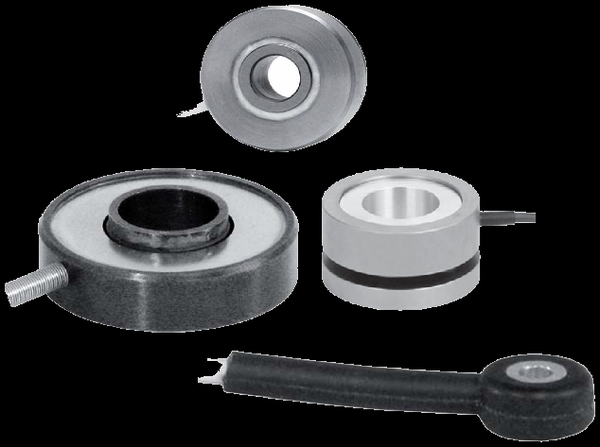
A donut (thru-hole) load cell measures compression through its centre hole — slip it over the bolt, stud, or rod and the clamping load reads out without breaking the load path. The WIKA-ST (legacy tecsis XLD) line spans four size tiers: subminiature XLD050/075 washers reading 100–1,000 g on a 1/4″ bolt, miniature XLD100/125 to 500 lb, standard XLD150–300 donuts to 100,000 lb, and the XLDB bolt sensor family keyed to standard bolt sizes to 300,000 lb for clamping-force and preload monitoring. Use the input form to send a tecsis part number and we cross-reference the current WIKA-ST equivalent.
Key Features & Benefits
- Reads the load without breaking the load path — the washer slips over the existing bolt, stud, or rod, so clamping force is measured in place — no re-fixturing, no dummy hardware in the stack. The tool for measuring a joint as built.
- Four size tiers from grams to 300,000 lb — subminiature gram-range washers for instrument and spring work, miniature and standard donuts for fixtures and presses, and bolt sensors keyed to standard bolt sizes from #2 to 2″. Pick the tier by the fastener, not the other way around.
- Low profile where there is no room for a cell — washer heights run from 0.15″ on the subminiature tier to 1″ at 100,000 lb, so the sensor disappears into the bolted stack. Force measurement in the space of a washer.
- Repeatability is the working spec on a bolt sensor — the XLDB trades absolute linearity for a ±0.1% FSO repeatability, which is what preload auditing actually uses — the same joint, the same sensor, tracked over time. Trend and comparison, measured honestly.
Specifications
- Operating principle
- A thru-hole (donut) compression cell — a strain-gauged washer that slips over a bolt, stud, or rod and reads the compressive load in the stack without breaking the load path. The XLDB bolt sensor is the same idea sized to standard bolts, placed under the head or nut to read bolt load directly.
- Force mode
- Compression — the load bears on the washer face through the fastener or rod that passes through the centre.
- Form factor & mounting
- Low-profile washers by tier: XLD050/075 subminiature, 0.50–0.75″ OD (fits up to a 1/4″ bolt); XLD100/125 miniature, 1.00–1.25″ OD (to a 3/8″ bolt); XLD150–300, 1.50–3.00″ OD (to a 1-1/2″ bolt); XLDB washers ID/OD-sized to standard bolts from #2 to 2″.
- Body / element material
- Stainless-steel casing; the XLDB in high-strength 440C stainless.
- Construction & sealing
- Solid washer element with an integral cable exit; the XLDB installs between hardened top and bottom washers with the chamfered bore face toward the bolt head.
- Capacity / measuring range
- XLD050/075: 100–1,000 g. XLD100/125: 5–500 lb. XLD150–300: 5–100,000 lb. XLDB: 500–300,000 lb, keyed to the bolt size (500 lb at #2 up to 300,000 lb at 2″).
- Output
- XLD050/075: 20 mV/V nominal (semiconductor gauges). XLD100/125 and XLD150–300: 2 mV/V nominal. XLDB: 2–4 mV/V.
- Excitation
- XLD050/075: 5 VDC. All larger tiers: 10 VDC (15 VDC max).
- Bridge resistance
- XLD050/075: 500 Ohms (semiconductor bridge). XLD100/125, XLD150–300, XLDB: 350 Ohms.
- Non-linearity
- XLD050/075 and XLD100/125: ±1.0% FSO combined linearity / hysteresis / repeatability. XLD150–300: ±0.5% FSO combined linearity + hysteresis. XLDB: linearity ±3.0% FSO (ranges under 30,000 lb) / ±4.0% FSO above — a bolt sensor reads trend and preload, not lab-grade force.
- Hysteresis
- XLDB: ±5.0% FSO (under 30,000 lb) / ±7.0% FSO above; the XLD donut tiers carry hysteresis inside their combined figure.
- Repeatability
- XLD150–300 and XLDB: ±0.1% FSO — the reason a coarse-linearity bolt sensor is still a dependable trend and comparison tool.
- Zero balance
- ±2% FSO (all tiers).
- Operating temperature range
- XLD050/075: −20 to +200°F. XLD100/125 and XLD150–300: −65 to +250°F. XLDB: −65 to +200°F.
- Compensated temperature range
- +60 to +160°F (XLDB +70 to +170°F).
- Thermal effects (zero / span)
- XLD100/125 and XLD150–300: on zero ±0.005% FSO/°F, on span ±0.010% reading/°F. XLD050/075: ±0.01% / ±0.02%. XLDB: ±0.01% FSO/°F zero and ±0.02% reading/°F span (under 18,000 lb; larger ranges tighter).
- Overload (safe / ultimate)
- Safe overload 150% of capacity (all tiers); ultimate 300% on the XLD donut tiers.
- Electrical connection
- 5 ft of 4-conductor cable (XLD tiers); the XLDB terminates in an MS3101A-14S-5P (or equivalent) connector on 5 ft of cable.
- Options
- Metric units available on every tier. Ordering is by outside diameter, capacity, and through-hole ID (not all combinations exist — we check the chart when we quote).
- Lead time & quotation
- Quote-only, no public price list; configured against the bolt or rod diameter, the capacity, and the temperature. Use the input form to send a legacy tecsis part number for a current WIKA-ST cross-reference.
Common Applications
- Bolt and stud clamping-force measurement — joint preload set and audited in place
- Bolt loading and preload monitoring on critical fasteners (XLDB under the head or nut)
- Overload monitoring where the force must pass through the sensor
- Clamp, fixture, and press force in tooling stacks
- Spring and instrument force on the gram-range subminiature tier
Design & Selection Considerations
- A bolt sensor changes the joint it measures — the washer adds height to the stack, and its ID/OD must match the bolt so the load bears on the sensing face — install the XLDB between its top and bottom washers with the chamfer toward the bolt head, then torque to the engineered preload. Use the input form to tell us the bolt size and grade and we match the washer, not just the capacity.
- Size the capacity to land the working load in the upper-middle of the range — aim for the routine load at roughly 50–90% of capacity: enough resolution and signal-to-noise, with headroom so peaks and transients never exceed the rating. Oversize and resolution suffers; undersize and an overload shifts the calibration. Account for shock and dynamic peaks, not just the static load.
- Keep the load axial, centered, and free of side load — most cells are rated for axial force only — an off-center or side load reads wrong and can damage the cell. Use the manufacturer’s load buttons / rod ends, keep the structure stiff and aligned, and on multi-cell arrays mount every cell coplanar. Most load-cell errors in the field are installation errors, not sensor errors.
- Read the accuracy terms the same way on every datasheet you compare — FSO quotes the error against full range, so a %FSO figure is a larger relative error at low load; BFSL reports linearity against a best-fit line. A ±0.03% cell is test-and-measurement grade, ±0.25–1% is industrial / OEM grade. Make sure two cells quote accuracy the same way before you compare them.
- Pick the output from what receives the signal and how far away it is — a raw mV/V bridge is right into a DAQ or indicator with bridge conditioning on a short, shielded run; an inline amplifier (4–20 mA or voltage) reads straight into a PLC and rides out long, noisy cable runs. Decide it from the receiver, not by default.
- Overload past safe but short of burst is the dangerous zone — safe overload (commonly 150% of capacity) is the load the cell can see without losing calibration; the ultimate rating is where it is destroyed. A cell overloaded between the two keeps reporting plausible, wrong numbers. Recalibrate after any suspected overload before you trust the data.
- Match the body material and temperature range to the environment — aluminum bodies are lighter and lower-cost; stainless resists corrosion and washdown; every cell has a compensated temperature band, with extended-temperature compensation available where the process runs hot or cold. Specify the environment up front and the material and compensation get built in.
To spec the right WIKA-ST donut load cell:
Use the input form to tell us the capacity (and the real worst-case peak), the force mode (tension, compression, or both), the accuracy class you need, how the load is introduced and how much room there is, the output (mV/V or amplified 4–20 mA / voltage) and the receiving device, the environment (temperature, washdown, hazardous area), and any calibration documentation or approval required (ASTM E74, OIML / NTEP). A legacy tecsis part number is enough to start — we cross-reference the current WIKA-ST equivalent.
Force & Pressure Application Sheet ›Talk to an engineer directly — Scott Prater, Principal · 917-580-0878 · scott@pratertechnical.com
Specifications compiled by Prater Technical Partners from WIKA product datasheets.