Product Overview
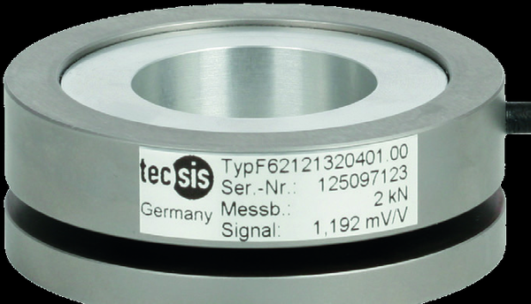
A ring force transducer reads force around a load that passes through it: the WIKA-ST F6212 is a flat, strain-gauged stainless ring with a large inner diameter, loaded axially on a ground surface while the spindle, ram, or bolt runs through the open centre (2–100 kN). Because the geometry is bought for repetitive press-in and joining strokes, the spec that matters is on the sheet: a 70% Fnom permissible cyclic stress per DIN 50100, with ≤0.5% Fnom linearity and a raw mV/V bridge or optional amplified output.
Key Features & Benefits
- A ring geometry where a standard cell will not fit — the open centre gives the shaft, spindle, or ram a way through, so nothing about the machine has to move to make room for the measurement. The form factor for when the load has to pass through the sensor.
- Rated for the repetitive stroke, not just the static hold — a 70% Fnom permissible cyclic stress per DIN 50100 means the ring is specified for the press-in and joining strokes it monitors shift after shift, not only a one-time reading. The spec that separates a monitoring transducer from a bench instrument.
- Raw bridge or finished signal — your choice — the standard bridge output feeds a DAQ or bridge-input indicator; the optional integrated or cable amplifier turns the same ring into a finished loop device. Either way, the mechanical fit does not change.
- A calibration-check function you can exercise in place — the optional control function injects a 100% signal so the measuring chain can be checked without unloading the press. A line check that does not stop the line.
Specifications
- Operating principle
- A strain-gauged ring loaded flat in the direct flux of force — the large inner diameter lets a shaft, spindle, or ram pass through the transducer while the force is read around it. Raw mV/V bridge standard, with an optional integrated or cable amplifier for a finished process signal.
- Capacity / measuring range
- 2, 5, 10, 20, 50, 100 kN rated force (0–2 kN up to 0–100 kN).
- Accuracy & repeatability
- Relative linearity error ≤0.5% Fnom; creep over 30 min <±0.1% Fnom; rated displacement <0.15 mm.
- Output & excitation
- 0.8–1.2 mV/V raw bridge standard (excitation DC 2–12 V, 15 V max; rated-output adjustment to 1 mV/V optional); optional integrated or cable amplifier to 0(4)–20 mA or DC 0–10 V (supply DC 12–28 V). Insulation resistance >2 GΩ.
- Overload & breaking force
- Force limit (safe overload) 150% Fnom; breaking force >300% Fnom.
- Dynamic / fatigue rating
- Permissible oscillation (cyclic) stress per DIN 50100: 70% Fnom — rated for the repetitive press and spindle strokes the ring geometry is bought for.
- Cross / transverse-force sensitivity
- Force must be applied axially, at right angles to the transducer, free of transverse force; connect the transducer electrically during installation and monitor the reading so mounting cannot silently overload it.
- Body material
- Stainless-steel measuring body; 1.1–1.4 kg.
- Sealing & protection class
- Protection class IP65 (IEC/EN 60529).
- Dimensions / fit
- Two body sizes: ranges 2–20 kN — approx. 70 mm OD × 25 mm high; ranges 50/100 kN — approx. 112 mm OD × 35 mm high. Optional fastening threads (M5×0.8 / M6×1) on the upper and lower faces.
- Mounting / load introduction
- A flat ring mounted on a flat, ground, hard surface, optionally bolted through the face threads; the open centre passes the spindle, bolt, or ram whose force is being read.
- Temperature range
- Rated temperature −10 to +50 °C; operating −30 to +80 °C; storage −50 to +95 °C. Extended nominal temperature range is an option.
- Thermal effect
- Temperature effect on zero and on characteristic value each <±0.2%/10 K.
- Approvals & options
- CE (EMC / RoHS). Options: control (calibration-check) function with 100% signal, 6-wire connection, extended nominal temperature range.
- Build & lead time
- Configured to order against the load, the ring size, the output, and the mounting. Quote-only — no public price list. Use the input form to send the load and the installation geometry and we return a configured quote and lead time.
Common Applications
- Press-in, joining, and press-spindle force monitoring — cutting tools, assembly cells
- Force measurement on spindle drives and press spindles through a ring with a large inner diameter
- Measurement and inspection equipment
- Test benches and production lines
- Repetitive-stroke monitoring using the 70% Fnom cyclic rating
Design & Selection Considerations
- Get the load axial, centered, and free of side load — these transducers measure force introduced straight down their axis. Take an off-center or transverse load and the reading is wrong and the element can be damaged — the datasheets call for a load that is axial, centric, and free of transverse force and torque. Most field errors here are load-introduction errors, not sensor errors.
- Size so the working load lands in the upper part of the range — aim to put the routine working load high enough in the range for good resolution and signal-to-noise, with headroom for peaks. Oversize and resolution suffers; undersize and an overload event shifts the calibration. Use the input form to tell us the static load and the worst-case peak — not just the nominal.
- Know the gap between safe overload and breaking force — every unit has a safe overload it can see without losing calibration and a higher breaking force where it is destroyed. The danger zone is between them: a unit overloaded past safe but not to breaking keeps reporting plausible, wrong numbers. Any suspected overload should trigger a recalibration before you trust the data again.
- Watch cross-sensitivity where the load can swing off-axis — a side load produces a real, specified error (the F5301, for example, carries a cross-sensitivity rating for load applied at 90°). Where the loading geometry can move — a swinging sheave, a misaligned fixture — account for it in the error budget or constrain the geometry. Off-axis load is a spec line for a reason.
- Pick the output to match what is reading the sensor — a raw mV/V bridge needs a conditioning input (DAQ or indicator with a bridge card); an integrated or cable amplifier reads straight into a PLC as 4–20 mA or 0–10 V. Use 4–20 mA for long, noisy runs; 0–10 V for short test-bench runs. Decide it from the receiver and the cable distance.
- A legacy tecsis part number cross-references to a current WIKA-ST unit — the tecsis force line is now built under WIKA Sensor Technology. Use the input form to send the tecsis part number and we match the current WIKA-ST equivalent at the same spec, so a field replacement does not require re-engineering the installation. No need to re-spec from scratch on a like-for-like swap.
To spec the right WIKA-ST ring force transducer:
To configure the right WIKA-ST force sensor, have these ready: the capacity (and the worst-case peak load); whether the force is tension, compression, or both; how the load is introduced (through an existing pin, a ring in the force path, or a threaded line); the output you need (4–20 mA, 0–10 V, mV/V, CANopen, or wireless) and the cable run; the environment (temperature, washdown, classified area); any certification (ATEX/IECEx, functional safety); and, for a load pin, the existing pin dimensions to match. A legacy tecsis part number is fine — send it and we cross-reference the current WIKA-ST equivalent.
Force & Pressure Application Sheet ›Talk to an engineer directly — Scott Prater, Principal · 917-580-0878 · scott@pratertechnical.com
Specifications compiled by Prater Technical Partners from WIKA product datasheets.