Product Overview
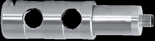
A load pin is a strain-gauged structural pin — you replace an existing clevis, sheave, or shackle pin with a dimensionally matched pin that carries the gauges, so the load is measured through hardware already in the load path, with nothing added to fixture. That makes it the standard tool for force in lifting, rigging, and crane safety: the tecsis F5301 series spans 0–5 kN to 0–200 kN with amplified 4–20 mA / 0–10 V output, and the wider WIKA-ST industrial load-pin program reaches roughly 200 tons with ATEX, IP67, and wireless / CANbus options for classified, outdoor, and moving-structure service.
Key Features & Benefits
- Measures the load through hardware that is already there — the gauges ride inside a structural pin that swaps for the one already carrying the load, so you read the actual force with nothing added to the rigging to fixture. The standard tool for force in lifting, rigging, and crane gear.
- Built to take shock, vibration, and the weather — a stainless body with high shock and vibration resistance, ATEX and IP-sealed options, and (on the wider lifting program) wireless or CANbus output for a moving structure. Spec for the classified, outdoor, or marine environment up front and it gets built in.
- Amplified output straight into the readout — the signal reads into a PLC or crane indicator without a separate bridge card, so the pin drops into the control system as a finished signal. No conditioning electronics to add.
- Dimensioned to your existing pin — the pin is configured to the bore it replaces, with a keeper-plate option for anti-rotation, so it simply drops into the gear it is replacing. Use the input form to send the bore dimensions and the capacity and it is built to fit.
Specifications
- Operating principle
- A strain-gauged structural pin — it replaces an existing clevis, sheave, or shackle pin with a dimensionally matched pin that carries strain gauges in a bore, so the load is measured through hardware already in the load path with no added fixturing. Built for static and dynamic force measurement.
- Capacity / measuring range
- Catalog measuring ranges 0–5 kN to 0–200 kN (roughly 0.5 to 20 tonne-force) in the F5301 series; the wider WIKA-ST industrial load-pin program extends to about 200 tons for crane, rigging, and terminal lifting. The pin is sized to the existing hardware dimensions, so capacity and fit are specified together.
- Accuracy & repeatability
- Linearity ±1.0% FSO (improved accuracy option) or ±2.0% FSO standard; hysteresis ±0.20% FSO; repeatability ±0.10% FSO (F5301).
- Output & excitation
- 4–20 mA (2-wire) or 0–10 VDC (3-wire) amplified output; excitation 10–30 VDC for current, 14–30 VDC for voltage. M12×1 connector (F5301). For lifting service, the wider WIKA-ST load-pin program also offers wireless and CANbus output where a moving structure makes a cable run impractical.
- Overload & breaking force
- Safe overload 150% of capacity; ultimate (breaking) overload 300% of capacity (F5301).
- Cross / transverse-force sensitivity
- Cross sensitivity (signal at 100% load applied at 90°) ±5.0% — the off-axis error a side load produces (F5301).
- Body material
- Stainless-steel casing (F5301).
- Dimensions / fit
- The pin is dimensioned to drop into the existing clevis, sheave, or shackle bore; the F5301 series is published with full ordering-code dimensions (pin diameter ØD, lengths, and fork-bearing geometry) per capacity, with a keeper-plate option for anti-rotation. All published in millimeters; American units also available. Use the input form to give us the bore dimensions to match.
- Mounting / load introduction
- Installed in a fork bearing / clevis with the measured force introduced as compression across the pin per DIN 15058; a fastening screw and optional keeper plate fix orientation so the gauged axis stays aligned to the load (F5301).
- Temperature range
- Operating temperature −40 to +80 °C; compensated temperature −20 to +80 °C (F5301).
- Thermal effect
- Thermal effect on zero and on span each 0.02% FSO/10 K (F5301).
- Approvals & options
- ATEX approval available; improved-accuracy and keeper-plate options (F5301). For classified lifting environments and outdoor / marine exposure the wider WIKA-ST load-pin program offers intrinsically-safe versions and IP67 sealing; for container terminals, spreader-bar four-corner arrays support SOLAS verified-gross-mass weighing.
- Build & lead time
- Configured to order against the existing pin dimensions, the capacity, the output, and the certification. Quote-only — no public price list. Use the input form to send the pin dimensions and the application and we return a configured quote and lead time.
Common Applications
- Crane, hoist, and rigging force — reading the actual lifted load through an existing sheave or shackle pin
- Container-terminal spreader-bar weighing in four-corner arrays — SOLAS verified-gross-mass
- Winch, draw-works, and line-tension monitoring on a moving structure (wireless / CANbus output)
- Overload and safe-load-indication systems on lifting equipment
- Test-bench and structural force measurement where a pin already carries the load path
Design & Selection Considerations
- Get the load axial, centered, and free of side load — these transducers measure force introduced straight down their axis. Take an off-center or transverse load and the reading is wrong and the element can be damaged — the datasheets call for a load that is axial, centric, and free of transverse force and torque. Most field errors here are load-introduction errors, not sensor errors.
- Size so the working load lands in the upper part of the range — aim to put the routine working load high enough in the range for good resolution and signal-to-noise, with headroom for peaks. Oversize and resolution suffers; undersize and an overload event shifts the calibration. Use the input form to tell us the static load and the worst-case peak — not just the nominal.
- Know the gap between safe overload and breaking force — every unit has a safe overload it can see without losing calibration and a higher breaking force where it is destroyed. The danger zone is between them: a unit overloaded past safe but not to breaking keeps reporting plausible, wrong numbers. Any suspected overload should trigger a recalibration before you trust the data again.
- Watch cross-sensitivity where the load can swing off-axis — a side load produces a real, specified error (the F5301, for example, carries a cross-sensitivity rating for load applied at 90°). Where the loading geometry can move — a swinging sheave, a misaligned fixture — account for it in the error budget or constrain the geometry. Off-axis load is a spec line for a reason.
- Pick the output to match what is reading the sensor — a raw mV/V bridge needs a conditioning input (DAQ or indicator with a bridge card); an integrated or cable amplifier reads straight into a PLC as 4–20 mA or 0–10 V. Use 4–20 mA for long, noisy runs; 0–10 V for short test-bench runs. Decide it from the receiver and the cable distance.
- A legacy tecsis part number cross-references to a current WIKA-ST unit — the tecsis force line is now built under WIKA Sensor Technology. Use the input form to send the tecsis part number and we match the current WIKA-ST equivalent at the same spec, so a field replacement does not require re-engineering the installation. No need to re-spec from scratch on a like-for-like swap.
To spec the right WIKA-ST load pin:
To configure the right WIKA-ST force sensor, have these ready: the capacity (and the worst-case peak load); whether the force is tension, compression, or both; how the load is introduced (through an existing pin, a ring in the force path, or a threaded line); the output you need (4–20 mA, 0–10 V, mV/V, CANopen, or wireless) and the cable run; the environment (temperature, washdown, classified area); any certification (ATEX/IECEx, functional safety); and, for a load pin, the existing pin dimensions to match. A legacy tecsis part number is fine — send it and we cross-reference the current WIKA-ST equivalent.
Force & Pressure Application Sheet ›Talk to an engineer directly — Scott Prater, Principal · 917-580-0878 · scott@pratertechnical.com
Specifications compiled by Prater Technical Partners from WIKA product datasheets.