Product Overview
A thin-film force transducer measures tension/compression in the direct flux of force with a gauge pattern sputter-deposited onto the stainless measuring body — no adhesive bond to creep over time. The WIKA-ST F2301 family runs 1 kN to 500 kN with integrated 4–20 mA / 0–10 V / CANopen output, a real ±50% Fnom cyclic-load rating, and functional-safety options: the dual-channel F23S1 for redundant safety circuits and the intrinsically-safe F23C1 for classified areas — the answer for dynamic, long-term, and safety-rated force measurement.
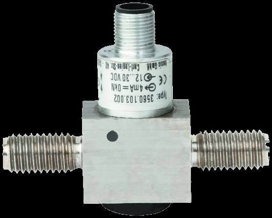
One thin-film platform, three nameplates
All three share the sputter-deposited gauge, the 1.4542 stainless body, IP67 sealing, and the ±50% Fnom cyclic rating — the nameplate picks the output and the certification.
- 4–20 mA (2-/3-wire) or DC 0–10 V integrated amplifier
- optional CANopen and optional redundant signal
- signal-jump version (4–16 mA, defined fault bands) for monitored safety circuits
- redundant opposing 4–20 / 20–4 mA channels
- two M12×1 connectors (one per channel)
- for safety circuits per the Machinery Directive 2006/42/EC
- ATEX / IECEx Ex ib version for classified areas
- 4–20 mA 2-wire only
- requires a galvanically isolated power supply
Key Features & Benefits
- Thin-film stability for long-term and dynamic duty — the gauge pattern is sputter-deposited onto the measuring body rather than adhesive-bonded, so there is no bond to creep over time — the basis for high long-term stability and a real ±50% Fnom cyclic-load rating. The answer when the reading has to stay true through dynamic or life-test service.
- Functional-safety output built in — the family carries a certified ELMS1 overload-protection rating to ISO 13849-1 PL d, with the dual-channel F23S1 delivering redundant opposing current signals, so it drops into a safety-rated machine as a qualified component. The certification a guarded press or hoist control expects.
- Threads into the line as a finished signal — the column becomes part of the linkage — ball / counter-nut load introduction, swivel heads for articulating lines — and the integrated amplifier reads straight into the control system as 4–20 mA, 0–10 V, or CANopen. No fixturing error, no conditioning electronics to add.
- Stainless and IP-sealed for the plant floor — a high-strength 1.4542 stainless body with IP67 sealing and reverse-voltage / short-circuit protection takes the chemistry, washdown, and electrical abuse of an industrial installation — with an ATEX/IECEx intrinsically-safe version for classified areas. Rugged where the duty is rough.
Specifications
- Operating principle
- A tension/compression column whose strain-gauge pattern is sputter-deposited (thin-film) onto the stainless measuring body. Threads into the loading line for static and dynamic measurement in the direct flux of force.
- Capacity / measuring range
- F2301: 1 kN to 500 kN (1, 2, 3, 5, 10, 20, 30, 50, 100, 200, 300, 500 kN). F23S1 dual-channel (redundant functional-safety) variant 3–100 kN; F23C1 intrinsically-safe variant 1–100 kN.
- Accuracy & repeatability
- Relative linearity error ±0.5% Fnom; reversibility error <0.1% Fnom; creep over 30 min 0.1% Fnom. Rated displacement typ. <0.02 mm (to 10 kN) / <0.2 mm (to 100 kN).
- Output & excitation
- F2301: integrated amplifier — 4–20 mA (2- or 3-wire) or DC 0–10 V, with optional CANopen (CiA 301, device profile 404) and optional redundant signal; a signal-jump version (4–16 mA with defined fault bands) serves monitored safety circuits. F23S1: redundant opposing 4–20 / 20–4 mA channels. F23C1: 4–20 mA 2-wire. Supply DC 10–30 V (current) / 14–30 V (voltage) / 12–30 V (CANopen); M12×1 connector (two connectors on the dual-channel F23S1).
- Overload & breaking force
- Force limit (safe overload) 150% Fnom; breaking force >300% Fnom.
- Dynamic / fatigue rating
- Permissible oscillation (cyclic) stress per DIN 50100: ±50% Fnom — the basis for dynamic and life-test duty rather than a single static reading.
- Cross / transverse-force sensitivity
- Force must be introduced axially, at right angles to the transducer, free of transverse force; vibration resistance 20 g, 50–150 Hz per DIN EN 60068-2-6.
- Body material
- High-strength corrosion-resistant stainless steel 1.4542, ultrasonically tested 3.1 material (3.2 optional).
- Sealing & protection class
- Protection class IP67 (EN/IEC 60529); reverse-voltage, overvoltage, and short-circuit protection built in.
- Dimensions / fit
- Connecting threads sized to the range — M12 at 1–10 kN up to M64×4 at 500 kN, each with a specified minimum screw-in depth; swivel heads per DIN ISO 12240-4 are available for articulating load lines.
- Mounting / load introduction
- Threads directly into the loading line (ball / counter-nut load introduction) for linear drives, machine building, hoists, and stage systems.
- Temperature range
- Rated temperature −20 to +80 °C; operating −30 to +80 °C (−40 °C optional); storage −40 to +85 °C.
- Thermal effect
- Temperature effect on zero and on characteristic value each 0.4% Fnom/10 K.
- Approvals & options
- ATEX/IECEx Ex ib intrinsically-safe version (F23C1; use a galvanically isolated supply); certified ELMS1 overload-protection product (DIN EN ISO 13849-1, PL d / Cat. 3) with redundant functional-safety output per the Machinery Directive 2006/42/EC; UL (component) and EAC options. Certificates, strength verifications, and 3D-CAD (STEP/IGES) on request.
- Build & lead time
- Configured to order against the load, the output, and any certification. Quote-only — no public price list. Use the input form to send the load and the installation geometry and we return a configured quote and lead time.
Common Applications
- Linear-drive and machine-building force in the direct flux of force
- Manufacturing automation — in-line force on a safety-rated machine (ELMS1 / redundant output)
- Theatre and stage construction — rigging and load monitoring
- Crane and hoist systems and industrial weighing technology
- Chemistry / petrochemistry — IP67 stainless, intrinsically-safe version for classified areas
- Dynamic and life-test rigs using the ±50% Fnom cyclic-load rating
Design & Selection Considerations
- Get the load axial, centered, and free of side load — these transducers measure force introduced straight down their axis. Take an off-center or transverse load and the reading is wrong and the element can be damaged — the datasheets call for a load that is axial, centric, and free of transverse force and torque. Most field errors here are load-introduction errors, not sensor errors.
- Size so the working load lands in the upper part of the range — aim to put the routine working load high enough in the range for good resolution and signal-to-noise, with headroom for peaks. Oversize and resolution suffers; undersize and an overload event shifts the calibration. Use the input form to tell us the static load and the worst-case peak — not just the nominal.
- Know the gap between safe overload and breaking force — every unit has a safe overload it can see without losing calibration and a higher breaking force where it is destroyed. The danger zone is between them: a unit overloaded past safe but not to breaking keeps reporting plausible, wrong numbers. Any suspected overload should trigger a recalibration before you trust the data again.
- Watch cross-sensitivity where the load can swing off-axis — a side load produces a real, specified error (the F5301, for example, carries a cross-sensitivity rating for load applied at 90°). Where the loading geometry can move — a swinging sheave, a misaligned fixture — account for it in the error budget or constrain the geometry. Off-axis load is a spec line for a reason.
- Pick the output to match what is reading the sensor — a raw mV/V bridge needs a conditioning input (DAQ or indicator with a bridge card); an integrated or cable amplifier reads straight into a PLC as 4–20 mA or 0–10 V. Use 4–20 mA for long, noisy runs; 0–10 V for short test-bench runs. Decide it from the receiver and the cable distance.
- A legacy tecsis part number cross-references to a current WIKA-ST unit — the tecsis force line is now built under WIKA Sensor Technology. Use the input form to send the tecsis part number and we match the current WIKA-ST equivalent at the same spec, so a field replacement does not require re-engineering the installation. No need to re-spec from scratch on a like-for-like swap.
To spec the right WIKA-ST thin-film force transducer:
To configure the right WIKA-ST force sensor, have these ready: the capacity (and the worst-case peak load); whether the force is tension, compression, or both; how the load is introduced (through an existing pin, a ring in the force path, or a threaded line); the output you need (4–20 mA, 0–10 V, mV/V, CANopen, or wireless) and the cable run; the environment (temperature, washdown, classified area); any certification (ATEX/IECEx, functional safety); and, for a load pin, the existing pin dimensions to match. A legacy tecsis part number is fine — send it and we cross-reference the current WIKA-ST equivalent.
Force & Pressure Application Sheet ›Talk to an engineer directly — Scott Prater, Principal · 917-580-0878 · scott@pratertechnical.com
Specifications compiled by Prater Technical Partners from WIKA product datasheets.