Product Overview
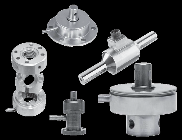
A multi-axis torque-thrust sensor measures two or more mechanical quantities in a single body on electrically isolated strain-gauge bridges — one per axis, each with its own connector and its own calibration — so the axes do not interfere and you avoid stacking separate single-axis sensors. The WIKA-ST (tecsis) builds resolve torque + axial thrust in one body, or three force axes (Fx, Fy, Fz), configured to the application’s load set. Choose multi-axis when the measuring point genuinely carries more than one load and you need each resolved cleanly; for a single static torque alone, the reaction torque sensor is simpler and lower-cost.
Key Features & Benefits
- No rotating parts to wear or signal across — because these are reaction / static sensors, the measurement is taken from a body that does not turn — so the wear items and the signal-coupling hardware a rotating torque sensor depends on simply are not present. Fewer failure points than a rotating torque sensor, and nothing to re-couple at maintenance.
- A stiff stainless element that holds calibration — the elastic element is machined stainless steel, so it deflects by a small, repeatable amount and returns to zero. The reading you trust on a test stand that runs for years.
- Sized to the torque you actually have — capacities start low — down to 0–25 in-oz (~1.5 in-lb) on the flange reaction design — so a small static torque lands in the upper part of the range where resolution is best, instead of using a sliver of an oversized sensor. Right-sized resolution for small and large torques alike.
- Reads into the bench you already have — the raw mV/V bridge output drops into any strain-gauge indicator or data-acquisition channel; where a PLC or a long cable run needs it, an external amplifier converts to 4–20 mA or a voltage signal. No proprietary readout required.
- Several loads at one point, without the cross-talk — the multi-axis build resolves torque and thrust — or three force axes — on separate, isolated bridges in one body, so the axes do not interfere and you avoid stacking single-axis sensors. One compact sensor where you would otherwise fixture three.
Specifications
- Measuring principle
- Strain-gauge multi-axis transducer — two or more quantities are measured in a single body on electrically isolated Wheatstone bridges, one per axis, each with its own connector. Resolving several loads at one point keeps the axes from interfering and removes the stack-up of separate single-axis sensors.
- Quantities measured
- Configurable. Two common builds: torque + axial thrust in one body (drawing 99-5946) and three force axes — Fx, Fy, Fz (the “Multi-Axis Load Cell,” drawing 99-3766). Each quantity is a separate, independently calibrated bridge.
- Torque measuring range
- Per the application — e.g. a catalog torque-thrust build (99-5946-0001) rated 750 ft-lbs torque with 15,000 lbs axial thrust in one body. Capacities are configured to the load set; tell us each axis’ full scale.
- Measurement axes
- Multiple, isolated. Torque + thrust (two channels) or Fx / Fy / Fz (three channels). On the 3-axis force build the Z-axis is compression-only; X and Y are the lateral force axes.
- Accuracy
- Torque-thrust build: ±0.25% FSO on both the torque and the thrust channel. 3-axis force build: ±0.5% FSO on the primary (Z) axis and ±2.0% FSO on the lateral (X, Y) axes. FSO = full-scale output.
- Output signal
- 2 to 3 mV/V nominal per bridge (torque-thrust); 2 mV/V nominal on the primary axis and 1.0 mV/V minimum on the lateral axes (3-axis force). Raw bridge output, one connector per axis.
- Excitation
- 10 VDC (15 VDC max), each bridge.
- Bridge resistance
- 350 Ω per bridge.
- Zero balance
- ±1.0% FSO per bridge (3-axis force build).
- Rotation
- Static / non-rotating measurement — the cable for each axis runs out of a stationary body; no slip rings.
- Mounting
- Bolted flange mount with a defined axis convention (the force directions and bolt circle are marked on the body); install so each measured load aligns with its labelled axis.
- Construction & material
- 17-4 PH stainless steel (torque-thrust build); stainless-steel body (3-axis force build).
- Overload capacity
- Safe overload 150% of capacity; ultimate overload 200% of capacity (3-axis force build).
- Operating temperature range
- −65 to +250°F.
- Compensated temperature range
- Torque-thrust build +10 to +140°F; 3-axis force build +30 to +120°F.
- Thermal effects
- On zero ±0.005% FSO/°F and on span ±0.005% reading/°F (torque-thrust); ±0.01% FSO/°F and ±0.01% reading/°F (3-axis force).
- Options & accessories
- Axis count, capacity per axis, calibration convention, and connector type are configured to the application; an external amplifier is available per channel where an amplified output is needed.
- Calibration & certification
- Each axis is independently calibrated against a traceable reference with a documented certificate. A legacy tecsis or Delta-Metric part number can be sent in for cross-reference to the current WIKA-ST equivalent.
Common Applications
- Combined torque-and-thrust measurement on a drive, propeller, or screw axis — one body, two channels
- Multi-component force resolution (Fx / Fy / Fz) at a single point — structural and R&D test rigs
- Drivetrain and propulsion testing — simultaneous torque and axial thrust
- Robotics and actuator multi-axis force / torque feedback
- Aerospace and defense component qualification under combined loads
Design & Selection Considerations
- Reaction vs. rotating — decide what is actually turning — a reaction sensor measures torque at a fixed mount and is right for test stands, motor and actuator characterization, and any rig where the torque can be reacted against ground. If you must measure torque on a continuously spinning shaft mid-drive, that is a rotating sensor, a different tool. Most bench and qualification work reacts to ground — confirm before you pick.
- Keep the load on-axis — off-axis loads corrupt the reading — a single-axis torque sensor is built to see torque, not bending or side thrust; an unintended off-axis load reads as error and can shift calibration. Where the application genuinely carries more than one load at the measuring point, specify the multi-axis build so each load is resolved on its own isolated bridge instead of polluting one channel. Match the number of measured axes to the number of real loads.
- Size for the worst-case torque, including transients — safe overload is 150% of capacity — exceed it and accuracy can shift invisibly while the sensor keeps reading plausible numbers; ultimate overload is where it is destroyed. Account for start-up snap, lock-up, and shock, not just the steady torque, and recalibrate after any suspected overload. The danger zone is between safe and ultimate — a sensor reading wrong but not broken.
- Mind the compensated band, not just the operating band — the sensor survives a wide operating range but is temperature-compensated over a narrower window; run it inside the compensated band for the rated accuracy, and budget the thermal-effect terms if the test temperature drifts. Accuracy is a compensated-range spec — read both numbers.
- Plan the readout with the sensor — the output is a low-level mV/V bridge signal — it needs proper bridge excitation and conditioning, a clean shielded run, and on the multi-axis build a channel per axis. Decide early whether the bench takes raw mV/V or needs an external amplifier for 4–20 mA / voltage. The wiring and channel count are a design decision, not an afterthought.
- Have a legacy tecsis or Delta-Metric part? Send it — these lines originated with tecsis / Delta Metrics and now ship under WIKA Sensor Technology. A legacy part number cross-references to the current WIKA-ST equivalent at the same spec — you do not have to re-engineer a drop-in. One part number in, the current equivalent out.
To spec the right WIKA-ST multi-axis torque-thrust cell:
Use the input form to send the quantities you need to measure (torque, and any combined thrust or force axes), the full-scale capacity for each axis, the required accuracy class, whether the readout takes a raw mV/V bridge signal or needs an amplified 4–20 mA / voltage output, the mounting interface, the operating and test temperatures, and any certification or calibration documentation required — and we will spec the right WIKA-ST torque sensor. Have a legacy tecsis or Delta-Metric part number? Send it and we will cross-reference the current WIKA-ST equivalent.
Force & Pressure Application Sheet ›Talk to an engineer directly — Scott Prater, Principal · 917-580-0878 · scott@pratertechnical.com
Specifications compiled by Prater Technical Partners from WIKA product datasheets.