Product Overview
WIKA-ST tension links measure pull by being part of the structure: a thin-film-gauged link plate, bolted in at both eyes, that serves as torque support, rope fixed point, or rigging member while reading the tension through it at ±0.5% Fnom with just ±2% shear sensitivity. The platform runs from 5 kN upward, dimensioned per application, in certified stainless or protected structural steel, sealed to IP69K plugged. Three nameplates: F7301 standard with the full output menu (redundant 4–20 mA, 0–10 V, signal-jump, CANopen), F73C1 for ATEX/IECEx Ex ib and Group I mining areas, and F73S1 whose opposing redundant channels form certified PL d / cat. 3 overload protection with the ELMS1 electronics. Built for crawler, mobile, and harbour cranes, winches, conveyors, and ship-lifting facilities.
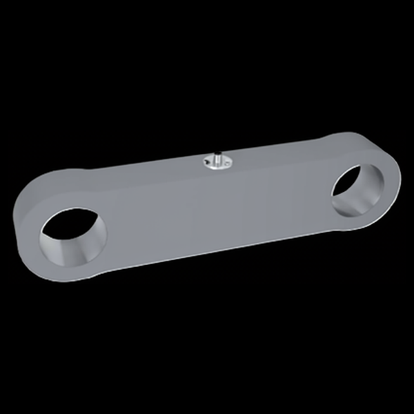
One link platform, three nameplates
All three share the thin-film element, the from-5-kN dimensioned-per-order build, the 150% / 300% overload margins, and the stainless-or-structural-steel choice — the nameplate picks the certification and the signal architecture.
- outputs: 4–20 mA (2-/3-wire), redundant 2×, 0–10 V, signal-jump, CANopen
- sealing to IP68 / IP69 / IP69K plugged
- M12, MIL, or cable-gland connection; UL component approval available
- ATEX / IECEx Ex ib IIC T4/T3 Gb; Ex I M2 mining (cable gland only); EAC Ex
- 4–20 mA 2-wire on DC 10–30 V; requires a galvanically isolated supply
- ATEX units labeled and certified under the tecsis brand; IP67
- redundant opposing 4–20 / 20–4 mA channels, one M12 per channel
- certified WIKA overload protection with ELMS1 — DIN EN ISO 13849-1 PL d / cat. 3 per the Machinery Directive
- 24-hour signal-jump self-test through the whole measuring chain
Key Features & Benefits
- A measuring member, not an added instrument — the link carries the load as part of the structure — torque support, rope fixed point, winch anchor — so the measurement adds a member the design already wanted instead of hardware it must accommodate. The force path barely notices the sensor is there.
- Half-percent linearity with low shear sensitivity — ±0.5% F-nom linearity plus a ±2% shear influence — markedly tighter than pin-style measurement — because the two-bolt link geometry keeps the load path where the gauges expect it. The form factor does part of the accuracy work.
- The crane-safety signal menu on a link — redundant opposing channels, daily signal-jump self-test (a defined 4-mA jump proves gauge-to-output every 24 hours, with cable break at 3.8 mA and short circuit at 21 mA detected), and CANopen for the machine bus — the same certified-overload architecture as the WIKA-ST pin program, in link form. Pick the geometry; keep the safety electronics.
- PL d / cat. 3 overload protection off the shelf — the F73S1 pairs with the ELMS1 safety electronics as WIKA-certified overload protection to DIN EN ISO 13849-1 PL d / category 3 under the Machinery Directive — a pre-certified safety loop for crawler, mobile, and harbour cranes. The certification is on the system, ready to inherit.
- Steel choice to match the budget and the weather — ultrasound-tested 1.4542 stainless with a 3.1 certificate where corrosion and traceability rule, or fine-grained structural steel with high-quality surface protection where they do not — same element, same electronics. Pay for stainless only where the site demands it.
Specifications
- Operating principle
- A load-bearing link plate with a thin-film strain bridge inside: bolts pass through both eyes and the link becomes a structural member of the rigging or machine, measuring the tension flowing through it — static and dynamic, in the direct flux of force, with the amplifier integrated.
- Capacity / measuring range
- Rated forces from 5 kN (1,124 lbf) upward — links are dimensioned per application, and the customer-specific drawing of the order takes priority.
- Accuracy & repeatability
- Relative linearity error ±0.5% Fnom; repeatability ±0.5% Fnom; rated displacement <0.1 mm (per VDI/VDE/DKD 2638).
- Output & excitation
- 4–20 mA (2- or 3-wire), redundant 2×4–20 mA, DC 0–10 V (single or redundant), signal-jump versions (4–16 mA / 2–8 V), and CANopen (CiA 301 / device profile 404). Supply DC 9–36 V; response 2 ms; reverse-polarity, overvoltage, and short-circuit protected.
- Overload & breaking force
- Force limit 150% Fnom; breaking force 300% Fnom.
- Cross / transverse-force sensitivity
- Shear-force influence ±2% Fnom (signal at 100% Fnom loaded at 90°) — less than half the load-pin figure, because a link constrains its own load path.
- Body material
- Choice of 1.4542 stainless (ultrasound-tested, 3.1 certificate; 3.2 available) or fine-grained structural steel with high-quality surface protection.
- Sealing & protection class
- Unplugged IP66/IP67; plugged IP68 / IP69 / IP69K (ATEX and safety versions: IP67).
- Mounting / load introduction
- Insert the bolts through both eyes and load in tension — the link is often the torque support or the rope fixed point. Shield/ground lands on a threaded hole. Connectors: M12×1 (4-/5-pin), MIL (MIL-CA3102E 16S-1P-B), or cable gland (ATEX); EZE53 molded-cable accessories in 2 / 5 / 10 m.
- Temperature range
- Rated −20 to +80°C; operating −30 to +80°C; storage −40 to +85°C.
- Thermal effect
- TK0 and TKC 0.2% Fnom/10 K.
- Approvals & options
- CE standard. F73C1: ATEX / IECEx Ex ib IIC T4/T3 Gb and Ex I M2 mining (cable gland only), EAC Ex, UL component approval on the family — ATEX units are labeled and certified under the tecsis brand, per the sheet. F73S1: functional safety per Machinery Directive 2006/42/EC as WIKA overload protection with the ELMS1 electronics (DIN EN ISO 13849-1, PL d / cat. 3). Vibration 20 g 100 h; shock per DIN EN 60068-2-27.
- Build & lead time
- Dimensioned per application from 5 kN up; configured by output, connector, material, and certification. Quote-only, no public price list.
Common Applications
- Crawler cranes, mobile cranes, and harbour cranes — recording load and torque
- Conveyor systems, drives, and winches — cable-winch measurement
- Ship-lifting facilities
- Rope fixed points and torque supports in special machine construction
- Certified overload-protection systems with ELMS1 (F73S1)
Design & Selection Considerations
- The link is a load-bearing member — treat it like one — it carries the structure’s load full-time, so bolt fit, bearing on the eyes, and the 150% / 300% margins belong in the structural review, and the order drawing governs the geometry. Design it in as steel first, instrument second.
- Pick the nameplate by the certification story — F7301 for general duty; F73C1 for classified areas (Ex ib needs a galvanically isolated repeater supply, and the mining mark requires the cable-gland build); F73S1 only as part of a functional-safety loop with ELMS1-class logic reading its opposing channels. The safety architecture and the link are one purchase.
- “From 5 kN” is a floor, not a ladder — the sheet publishes the platform’s lower bound and leaves capacity to the application — send the working load, the peak, and the eye/bolt geometry and the factory dimensions the link. Capacity is an output of the review, not a catalog row.
- Get the load axial, centered, and free of side load — these transducers measure force introduced straight down their axis. Take an off-center or transverse load and the reading is wrong and the element can be damaged — the datasheets call for a load that is axial, centric, and free of transverse force and torque. Most field errors here are load-introduction errors, not sensor errors.
- Size so the working load lands in the upper part of the range — aim to put the routine working load high enough in the range for good resolution and signal-to-noise, with headroom for peaks. Oversize and resolution suffers; undersize and an overload event shifts the calibration. Use the input form to tell us the static load and the worst-case peak — not just the nominal.
- Know the gap between safe overload and breaking force — every unit has a safe overload it can see without losing calibration and a higher breaking force where it is destroyed. The danger zone is between them: a unit overloaded past safe but not to breaking keeps reporting plausible, wrong numbers. Any suspected overload should trigger a recalibration before you trust the data again.
- Watch cross-sensitivity where the load can swing off-axis — a side load produces a real, specified error (the F5301, for example, carries a cross-sensitivity rating for load applied at 90°). Where the loading geometry can move — a swinging sheave, a misaligned fixture — account for it in the error budget or constrain the geometry. Off-axis load is a spec line for a reason.
- Pick the output to match what is reading the sensor — a raw mV/V bridge needs a conditioning input (DAQ or indicator with a bridge card); an integrated or cable amplifier reads straight into a PLC as 4–20 mA or 0–10 V. Use 4–20 mA for long, noisy runs; 0–10 V for short test-bench runs. Decide it from the receiver and the cable distance.
- A legacy tecsis part number cross-references to a current WIKA-ST unit — the tecsis force line is now built under WIKA Sensor Technology. Use the input form to send the tecsis part number and we match the current WIKA-ST equivalent at the same spec, so a field replacement does not require re-engineering the installation. No need to re-spec from scratch on a like-for-like swap.
To spec the right WIKA-ST tension link:
To configure the right WIKA-ST force sensor, have these ready: the capacity (and the worst-case peak load); whether the force is tension, compression, or both; how the load is introduced (through an existing pin, a ring in the force path, or a threaded line); the output you need (4–20 mA, 0–10 V, mV/V, CANopen, or wireless) and the cable run; the environment (temperature, washdown, classified area); any certification (ATEX/IECEx, functional safety); and, for a load pin, the existing pin dimensions to match. A legacy tecsis part number is fine — send it and we cross-reference the current WIKA-ST equivalent.
Force & Pressure Application Sheet ›Talk to an engineer directly — Scott Prater, Principal · 917-580-0878 · scott@pratertechnical.com
Specifications compiled by Prater Technical Partners from WIKA product datasheets.