Product Overview
WIKA-ST heavy-duty load pins gauge the pin that is already carrying the load — in the pulley, the winch frame, the fork bearing — at the ratings harsh machines need: force limit 200%, breaking force 500% of rated, from 10 kN up, in ultrasound-tested 1.4542 stainless with a 3.1 certificate. The platform carries three nameplates: the F5308 standard with every output from redundant 4–20 mA to CANopen, the F53C8 with ATEX/IECEx in both Ex ib and Ex d plus UL, EAC Ex, and optional DNV, and the F53S8 whose opposing redundant channels pair with the ELMS1 electronics as certified PL d / cat. 3 overload protection. Sealing reaches IP69K plugged; response is 2 ms; and every pin is machined to your joint’s drawing.
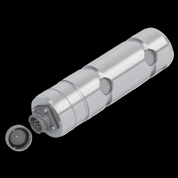
One heavy-duty pin platform, three nameplates
All three share the thin-film element, 1.4542 ultrasound-tested stainless with 3.1 certificate, 200% / 500% overload margins, and the DIN 15058 mounting — the nameplate picks the certification and the signal architecture.
- outputs: 4–20 mA (2-/3-wire), redundant 2×, 0–10 V, signal-jump, CANopen
- sealing to IP68 / IP69 / IP69K plugged
- M12, MIL, or cable-gland connection
- ATEX / IECEx Ex ib (incl. Ex I M2 mining) AND Ex d (cable gland)
- UL component approval; EAC Ex; optional DNV ships/offshore
- 4–20 mA 2-wire on DC 10–30 V; Ex ib requires a galvanically isolated supply; IP67
- redundant opposing 4–20 / 20–4 mA channels, one M12 per channel
- certified WIKA overload protection with ELMS1 — DIN EN ISO 13849-1 PL d / cat. 3 per the Machinery Directive
- 24-hour signal-jump self-test through the whole measuring chain
Key Features & Benefits
- Heavy-duty means the overload numbers, not the paint — force limit 200% and breaking force 500% of rated — roughly double the margins of a standard pin — because winches, offshore gear, and mobile machines deliver their worst loads through exactly this joint. The tier is defined by what it survives.
- A safety loop that tests itself every day — the signal-jump electronics switch a test resistor across the bridge on command, producing a defined 4-mA jump the controller verifies at 24-hour intervals — proving the whole path from gauge to output, with cable break at 3.8 mA and short circuit at 21 mA detected by design. The overload circuit audits itself while the crane sleeps.
- PL d / cat. 3 overload protection as a catalog item — the F53S8’s redundant opposing channels (4–20 / 20–4 mA) pair with the ELMS1 safety electronics to form a certified Machinery-Directive overload system — the safety case arrives engineered instead of assembled from parts. Buy the architecture, not just the sensor.
- Ex ib AND Ex d on one platform — the F53C8 covers both protection philosophies — intrinsically safe for the instrument loop and flameproof with a cable gland where the power budget will not fit ib — plus the Ex I M2 mining mark and optional DNV ships/offshore approval. One pin family clears gas, mining, and marine reviews.
- Certified steel with the paperwork attached — 1.4542 stainless, ultrasound-tested, delivered with a 3.1 certificate (3.2 available) — the material traceability that lifting-gear reviews and classification societies ask for, standard. The pin arrives with its pedigree.
Specifications
- Operating principle
- A thin-film strain-gauged structural pin that replaces a non-measuring bolt in a pulley, winch, or fork bearing — the heavy-duty tier of the WIKA-ST load-pin program, for static and dynamic tension and/or compression under harsh conditions, with the amplifier integrated in the pin.
- Capacity / measuring range
- Rated forces from 10 kN (2,248 lbf) upward — each pin is built to the joint, and the customer-specific load-pin drawing of the order takes priority over the catalog dimensions.
- Accuracy & repeatability
- Relative linearity error ±1% / ±1.5% Fnom by build; repeatability ±0.2% Fnom at unchanged mounting; rated displacement <0.1 mm (per VDI/VDE/DKD 2638).
- Output & excitation
- The full WIKA-ST amplified menu: 4–20 mA (2- or 3-wire), redundant 2×4–20 mA, DC 0–10 V (single or redundant), signal-jump versions (4–16 mA / 2–8 V), and CANopen (CiA 301, device profile 404). Supply DC 9–36 V; response 2 ms.
- Overload & breaking force
- Force limit 200% Fnom; breaking force 500% Fnom — the heavy-duty margins that separate this tier from the standard pin program.
- Cross / transverse-force sensitivity
- Shear-force influence ±5% Fnom (signal at 100% Fnom loaded at 90°).
- Body material
- Corrosion-resistant stainless steel 1.4542, ultrasound-tested, with a 3.1 material certificate (3.2 version available).
- Sealing & protection class
- Unplugged IP66/IP67; plugged IP68 / IP69 / IP69K (ATEX and safety versions: IP67).
- Mounting / load introduction
- Pin retainer per DIN 15058 with fastening screw and marked force direction; M6 ground connection. Connectors: M12×1 (4-/5-pin), MIL (MIL-CA3102E 16S-1P-B), or cable gland (Ex d); EZE53 molded-cable accessories in 2 / 5 / 10 m.
- Temperature range
- Rated −20 to +80°C (a −40 to +120°C build is listed with the UL scope); operating −30 to +80°C; storage −40 to +85°C.
- Thermal effect
- TK0 and TKC 0.2% Fnom/10 K.
- Approvals & options
- CE standard. F53C8: ATEX / IECEx in BOTH Ex ib (intrinsically safe, incl. Ex I M2 mining with cable gland) and Ex d (flameproof, cable gland only); UL component approval; EAC Ex; optional DNV (DNV-ST-0377/-0378, ships and offshore). F53S8: functional safety per Machinery Directive 2006/42/EC as WIKA overload protection with the ELMS1 electronics (DIN EN ISO 13849-1, PL d / cat. 3). Vibration 20 g 100 h; shock per DIN EN 60068-2-27.
- Build & lead time
- Every pin is dimensioned to the existing joint — the order drawing governs. Configured per capacity, output, connector, and certification. Quote-only, no public price list.
Common Applications
- Crane systems, hoists, offshore, and mobile working machines
- Industrial weighing technology — weighing in safety applications
- Machine building, plant construction, and manufacturing automation
- Chemical and petrochemical industries — classified-area lifting points (F53C8)
- Certified overload-protection systems with ELMS1 (F53S8)
Design & Selection Considerations
- The order drawing governs — capture the joint completely — the datasheet says it plainly: the customer-specific load-pin drawing has priority. Pin diameter, groove and retainer per DIN 15058, force direction, and the mating bore tolerances all come from your joint — survey it before the RFQ. The pin is a machined copy of your hardware with a sensor inside.
- Pick the nameplate by the certification story — F5308 for general duty, F53C8 for classified areas (choose Ex ib vs Ex d by the loop design — ib needs a galvanically isolated repeater supply), F53S8 only as part of a functional-safety loop with ELMS1-class logic. The electronics decision and the pin decision are one decision. Certification is a system property.
- Shear direction is part of the calibration — a load pin reads the force direction it was gauged for, and off-axis load contributes the published ±5% shear influence — the force-direction mark and the DIN 15058 retainer exist to keep the pin oriented. A rotated pin is a miscalibrated pin.
- Get the load axial, centered, and free of side load — these transducers measure force introduced straight down their axis. Take an off-center or transverse load and the reading is wrong and the element can be damaged — the datasheets call for a load that is axial, centric, and free of transverse force and torque. Most field errors here are load-introduction errors, not sensor errors.
- Size so the working load lands in the upper part of the range — aim to put the routine working load high enough in the range for good resolution and signal-to-noise, with headroom for peaks. Oversize and resolution suffers; undersize and an overload event shifts the calibration. Use the input form to tell us the static load and the worst-case peak — not just the nominal.
- Know the gap between safe overload and breaking force — every unit has a safe overload it can see without losing calibration and a higher breaking force where it is destroyed. The danger zone is between them: a unit overloaded past safe but not to breaking keeps reporting plausible, wrong numbers. Any suspected overload should trigger a recalibration before you trust the data again.
- Watch cross-sensitivity where the load can swing off-axis — a side load produces a real, specified error (the F5301, for example, carries a cross-sensitivity rating for load applied at 90°). Where the loading geometry can move — a swinging sheave, a misaligned fixture — account for it in the error budget or constrain the geometry. Off-axis load is a spec line for a reason.
- Pick the output to match what is reading the sensor — a raw mV/V bridge needs a conditioning input (DAQ or indicator with a bridge card); an integrated or cable amplifier reads straight into a PLC as 4–20 mA or 0–10 V. Use 4–20 mA for long, noisy runs; 0–10 V for short test-bench runs. Decide it from the receiver and the cable distance.
- A legacy tecsis part number cross-references to a current WIKA-ST unit — the tecsis force line is now built under WIKA Sensor Technology. Use the input form to send the tecsis part number and we match the current WIKA-ST equivalent at the same spec, so a field replacement does not require re-engineering the installation. No need to re-spec from scratch on a like-for-like swap.
To spec the right WIKA-ST heavy-duty load pin:
To configure the right WIKA-ST force sensor, have these ready: the capacity (and the worst-case peak load); whether the force is tension, compression, or both; how the load is introduced (through an existing pin, a ring in the force path, or a threaded line); the output you need (4–20 mA, 0–10 V, mV/V, CANopen, or wireless) and the cable run; the environment (temperature, washdown, classified area); any certification (ATEX/IECEx, functional safety); and, for a load pin, the existing pin dimensions to match. A legacy tecsis part number is fine — send it and we cross-reference the current WIKA-ST equivalent.
Force & Pressure Application Sheet ›Talk to an engineer directly — Scott Prater, Principal · 917-580-0878 · scott@pratertechnical.com
Specifications compiled by Prater Technical Partners from WIKA product datasheets.