Product Overview
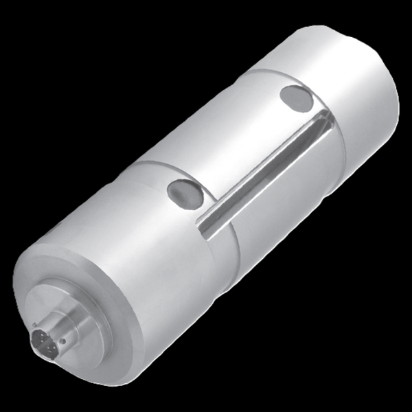
The tecsis XLPD dual load pin (now WIKA Sensor Technology) is the high-accuracy load pin: a strain-gauged replacement pin for sheaves, pulleys, and shackle points whose patent-pending design cancels the loading-induced error that limits ordinary pins, reaching ±0.25% FSO combined (application-dependent — the factory confirms the figure for your pin-diameter ratio). Standard builds cover 0–150 kN, with the published curve extending to ~300,000 lbf on 20–150-mm pins. Welded stainless, IP67, −54 to +121°C, shock-rated, mV/V or internally amplified — created for harbor cranes and straddle carriers, accurate enough that the same pin serves crane weighing.
Key Features & Benefits
- Attacks the error the datasheets usually ignore — a conventional load pin is only as accurate as the way the load happens to sit on it — rope angle, bearing wear, and fit scatter the reading. The XLPD’s patent-pending design cancels the loading-induced component, which is why its combined figure reaches 0.25% where standard pins quote 1–2%. The accuracy gain is in the physics, not the calibration certificate.
- Crane-born, weighing-grade — created for harbor cranes and straddle carriers, the XLPD reads well enough to serve weighing applications from the same pin — one sensor covers the safety interlock and the logged load value. Overload protection that is also a measurement.
- Nothing added to the machine — like every load pin, it measures through hardware already in the load path — the sheave pin, the padeye pin — so the crane’s geometry, headroom, and certified structure stay untouched. The retrofit is invisible until you look at the connector.
- Sized to the joint, not to a catalog row — the published curve spans pin diameters of 20–150 mm and capacities to roughly 300,000 lbf, and each unit is built to the application drawing — the pin you need is the pin you have, gauged. Use the input form to send the pin drawing; the sensor comes back matching it.
- Arctic-to-tropic survival envelope — operating from −54 to +121°C in welded stainless at IP67, with shock-load design margin — the outdoor, salt-air, all-season duty of port equipment is the design case, not an extrapolation. Built for the quayside it was invented on.
Specifications
- Operating principle
- A strain-gauged structural pin that replaces the existing pin in a sheave, pulley, or shackle point — with a patent-pending dual design whose point is accuracy: most load-pin error comes from variation in how the load lands on the pin, and the XLPD’s design virtually eliminates that loading-induced error.
- Capacity / measuring range
- Standard range 0–150 kN (16 ton); the published capacity-vs-pin-diameter curve runs to roughly 300,000 lbf on pins 20–150 mm — every XLPD is built to the application’s pin, so the factory review sets the real figure.
- Accuracy & repeatability
- Up to 0.25%: linearity + hysteresis ±0.25% FSO combined, repeatability ±0.1% FSO — with the sheet’s own qualifier that true accuracy depends on the load-range-to-pin-diameter ratio and is confirmed at application review.
- Output & excitation
- 2 mV/V nominal on a 350-Ω bridge, 10 VDC excitation (15 V max); internal amplification available for a conditioned signal.
- Overload & breaking force
- Safe overload 150% of capacity; maximum 300%. Designed to handle high shock loads.
- Body material
- Rugged, welded stainless steel.
- Sealing & protection class
- IP67.
- Dimensions / fit
- Application-specific — the drawing is generated per order to match the pin diameter, grooves, and retention of the joint it replaces.
- Mounting / load introduction
- Installs through the sheave, pulley, or padeye exactly as the pin it replaces; created originally for harbor cranes and mobile and stationary straddle cranes.
- Temperature range
- Operating −54 to +121°C (−65 to +250°F); compensated +15 to +71°C.
- Thermal effect
- Zero ±0.005% FSO/°F; span ±0.005% of reading/°F; fully temperature compensated.
- Approvals & options
- cCSAus mark; RoHS; ISO 9001-registered manufacture; high EMC resistance.
- Build & lead time
- Every XLPD is application-engineered — capacity, pin geometry, and output are set in the factory review of your sheave or shackle drawing. Quote-only, no public price list.
Common Applications
- Harbor cranes and mobile / stationary straddle cranes — the XLPD’s original application
- Crane weighing — logged load values off the sheave pin
- Sheave, pulley, and padeye load monitoring where standard pin accuracy is not enough
- Overload protection with a measurement-grade signal
Design & Selection Considerations
- “Up to 0.25%” has an engineering condition attached — the sheet itself says true accuracy depends on the load range and the pin-diameter ratio, with factory review setting the final spec — a small load on a fat pin cannot reach the headline figure. Treat 0.25% as what the design can achieve when the geometry cooperates. The review is where the number becomes yours.
- Note the compensated band vs the operating band — the pin survives −54 to +121°C but is temperature-compensated +15 to +71°C — outside the compensated band the reading drifts by the published coefficients. A cold-climate precision application should put that drift in the error budget. Two temperature ranges, two meanings.
- Plan the signal chain at order time — the base output is 2 mV/V — a bridge input or the optional internal amplification decides how it reaches the PLC, and the choice affects the cable run and the connector. Decide the readout with the pin, not after it ships.
- Get the load axial, centered, and free of side load — these transducers measure force introduced straight down their axis. Take an off-center or transverse load and the reading is wrong and the element can be damaged — the datasheets call for a load that is axial, centric, and free of transverse force and torque. Most field errors here are load-introduction errors, not sensor errors.
- Size so the working load lands in the upper part of the range — aim to put the routine working load high enough in the range for good resolution and signal-to-noise, with headroom for peaks. Oversize and resolution suffers; undersize and an overload event shifts the calibration. Use the input form to tell us the static load and the worst-case peak — not just the nominal.
- Know the gap between safe overload and breaking force — every unit has a safe overload it can see without losing calibration and a higher breaking force where it is destroyed. The danger zone is between them: a unit overloaded past safe but not to breaking keeps reporting plausible, wrong numbers. Any suspected overload should trigger a recalibration before you trust the data again.
- Watch cross-sensitivity where the load can swing off-axis — a side load produces a real, specified error (the F5301, for example, carries a cross-sensitivity rating for load applied at 90°). Where the loading geometry can move — a swinging sheave, a misaligned fixture — account for it in the error budget or constrain the geometry. Off-axis load is a spec line for a reason.
- Pick the output to match what is reading the sensor — a raw mV/V bridge needs a conditioning input (DAQ or indicator with a bridge card); an integrated or cable amplifier reads straight into a PLC as 4–20 mA or 0–10 V. Use 4–20 mA for long, noisy runs; 0–10 V for short test-bench runs. Decide it from the receiver and the cable distance.
- A legacy tecsis part number cross-references to a current WIKA-ST unit — the tecsis force line is now built under WIKA Sensor Technology. Use the input form to send the tecsis part number and we match the current WIKA-ST equivalent at the same spec, so a field replacement does not require re-engineering the installation. No need to re-spec from scratch on a like-for-like swap.
To spec the right WIKA-ST dual load pin:
To configure the right WIKA-ST force sensor, have these ready: the capacity (and the worst-case peak load); whether the force is tension, compression, or both; how the load is introduced (through an existing pin, a ring in the force path, or a threaded line); the output you need (4–20 mA, 0–10 V, mV/V, CANopen, or wireless) and the cable run; the environment (temperature, washdown, classified area); any certification (ATEX/IECEx, functional safety); and, for a load pin, the existing pin dimensions to match. A legacy tecsis part number is fine — send it and we cross-reference the current WIKA-ST equivalent.
Force & Pressure Application Sheet ›Talk to an engineer directly — Scott Prater, Principal · 917-580-0878 · scott@pratertechnical.com
Specifications compiled by Prater Technical Partners from WIKA product datasheets.