Product Overview
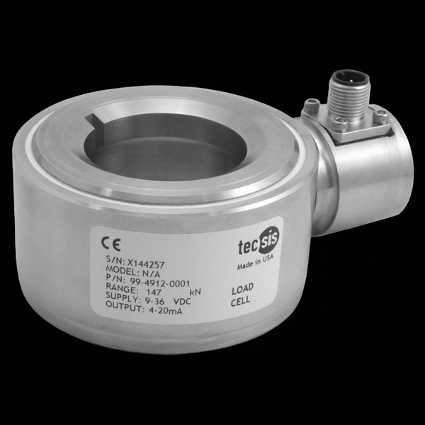
The tecsis XLCS spreader load cell (now WIKA Sensor Technology) puts container weighing inside the twist lock: an annular stainless compression cell rated 0–15 t per corner sits between the actuator arm and the twist lock, reading every lift in real time on mobile and stationary container-handling equipment. Welded stainless, IP67, side-load and shock resistant, compensated across −40 to +80°C, and qualified to the DIN EN 60068 environmental series with automotive-grade EMC — with an amplified 4–20 mA output the crane PLC reads directly. Four corners of XLCS give a spreader a per-lift gross weight — the measurement underneath verified-gross-mass workflows — without a weighbridge in the traffic lane.
Key Features & Benefits
- Weighs the box during the move it was already making — the cell lives between actuator arm and twist lock, so the container’s weight is captured in-cycle on the lift itself — no separate weighbridge stop, no second handling of the box. The weighing step disappears into the lift.
- Qualified like vehicle equipment, because it rides one — the datasheet cites the full DIN EN 60068 environmental series — climate, sinusoidal vibration, shock, drop — plus automotive-grade EMC (DIN ISO 11452 / 7637): the qualification set for hardware that lives on a moving reach stacker, not on a lab bench. Tested for the machine it bolts to.
- Shrugs off the corner-casting slam — twist locks land hard and off-center by nature; the XLCS is specified resistant to side loading and high shock, with supplied top and bottom washers ensuring the load introduces properly every engagement. Designed around how spreaders actually hit boxes.
- PLC-ready signal from a hostile place — an amplified 4–20 mA loop on 9–36 VDC runs the length of a spreader harness through crane EMI without a conditioning cabinet — one M12 plug per corner. Four cells, four loops, one summed weight in the PLC.
- Full-envelope temperature compensation — compensated across the entire −40 to +80°C operating range — not a narrow compensated band inside a wider survival range — so winter-terminal and summer-deck readings carry the same error budget. The port does not have a compensated season.
Specifications
- Operating principle
- An annular compression load cell engineered to integrate into the twist-lock assembly of a container spreader — the stack is actuator arm, XLCS cell, twist lock — so every container lift is weighed in real time through the hardware that picks it up.
- Capacity / measuring range
- 0–15 tonnes per cell (one cell per twist-lock corner).
- Accuracy & repeatability
- Linearity ±0.5% FSO; hysteresis ±0.5% FSO; repeatability ±0.1% FSO; zero balance ±1.0% FSO.
- Output & excitation
- Amplified 4–20 mA, 3-wire, on 9–36 VDC — straight into the crane PLC with no external conditioning. M12×1 connector; short-circuit and reverse-polarity protected; high EMC resistance.
- Overload & breaking force
- Safe overload 150% of capacity; maximum 300%.
- Cross / transverse-force sensitivity
- Designed to be resistant to side loading and high shock — the loading reality of a spreader slamming onto container corner castings.
- Body material
- Rugged, welded stainless steel.
- Sealing & protection class
- IP67.
- Mounting / load introduction
- Installs in the twist-lock stack with application-specific top and bottom washers (supplied) to ensure proper loading; customer-specified designs available.
- Temperature range
- Operating and compensated −40 to +80°C (−40 to +176°F) — fully temperature compensated across the whole envelope.
- Thermal effect
- Zero ±0.009% FSO/°C; span ±0.009% of reading/°C.
- Approvals & options
- cCSAus mark; RoHS; environmental qualification per DIN EN 60068 (climate -2-30, vibration -2-6, shock -27/-29, drop -2-31) and EMC per DIN EN 61000-4 / DIN ISO 11452 / DIN ISO 7637.
- Build & lead time
- Configured per spreader — the twist-lock geometry sets the build, and the supplied loading washers are application-specific. Quote-only, no public price list.
Common Applications
- Cargo-container weighing on spreaders — mobile and stationary container-lifting equipment
- Reach stackers and straddle carriers — per-lift gross weight in the cab
- Verified-gross-mass (container weight verification) workflows at terminals
- Overload protection on container-handling attachments
Design & Selection Considerations
- The twist-lock geometry drives the build — the XLCS is integrated into a specific spreader’s twist-lock stack, and the sheet is explicit that designs are customer-specified with application-specific loading washers supplied — send the spreader / twist-lock drawings with the inquiry. This is a fitted part, not a shelf part.
- Corner weights need summing — and sanity checks — a container’s gross weight is the sum of four corner cells reading an eccentric, shifting load; the crane control must sum the loops and flag a stuck or failed corner. Plan the logic with the cells. The weight is a system output, not a sensor output.
- Regulatory acceptance is the buyer’s workflow — the XLCS provides the measurement; whether a terminal’s verified-gross-mass method is accepted (weighing method, tolerance, documentation) is set by the flag state and terminal procedure. Confirm the compliance path in parallel with the hardware. The cell is necessary, the paperwork is separate.
- Get the load axial, centered, and free of side load — these transducers measure force introduced straight down their axis. Take an off-center or transverse load and the reading is wrong and the element can be damaged — the datasheets call for a load that is axial, centric, and free of transverse force and torque. Most field errors here are load-introduction errors, not sensor errors.
- Size so the working load lands in the upper part of the range — aim to put the routine working load high enough in the range for good resolution and signal-to-noise, with headroom for peaks. Oversize and resolution suffers; undersize and an overload event shifts the calibration. Use the input form to tell us the static load and the worst-case peak — not just the nominal.
- Know the gap between safe overload and breaking force — every unit has a safe overload it can see without losing calibration and a higher breaking force where it is destroyed. The danger zone is between them: a unit overloaded past safe but not to breaking keeps reporting plausible, wrong numbers. Any suspected overload should trigger a recalibration before you trust the data again.
- Watch cross-sensitivity where the load can swing off-axis — a side load produces a real, specified error (the F5301, for example, carries a cross-sensitivity rating for load applied at 90°). Where the loading geometry can move — a swinging sheave, a misaligned fixture — account for it in the error budget or constrain the geometry. Off-axis load is a spec line for a reason.
- Pick the output to match what is reading the sensor — a raw mV/V bridge needs a conditioning input (DAQ or indicator with a bridge card); an integrated or cable amplifier reads straight into a PLC as 4–20 mA or 0–10 V. Use 4–20 mA for long, noisy runs; 0–10 V for short test-bench runs. Decide it from the receiver and the cable distance.
- A legacy tecsis part number cross-references to a current WIKA-ST unit — the tecsis force line is now built under WIKA Sensor Technology. Use the input form to send the tecsis part number and we match the current WIKA-ST equivalent at the same spec, so a field replacement does not require re-engineering the installation. No need to re-spec from scratch on a like-for-like swap.
To spec the right WIKA-ST spreader load cell:
To configure the right WIKA-ST force sensor, have these ready: the capacity (and the worst-case peak load); whether the force is tension, compression, or both; how the load is introduced (through an existing pin, a ring in the force path, or a threaded line); the output you need (4–20 mA, 0–10 V, mV/V, CANopen, or wireless) and the cable run; the environment (temperature, washdown, classified area); any certification (ATEX/IECEx, functional safety); and, for a load pin, the existing pin dimensions to match. A legacy tecsis part number is fine — send it and we cross-reference the current WIKA-ST equivalent.
Force & Pressure Application Sheet ›Talk to an engineer directly — Scott Prater, Principal · 917-580-0878 · scott@pratertechnical.com
Specifications compiled by Prater Technical Partners from WIKA product datasheets.