Product Overview
WIKA-ST wire-rope tension cells read the force in a steel rope by clamping onto it — the retrofit answer for crane and hoist overload protection and rope-tension measurement on equipment that is already built and reeved. The F9204 is the alloyed-steel workhorse: 1 to 40 t, IP66, 4–20 mA from an integrated amplifier on a fixed cable. The F9304 / F93C4 family is the stainless upgrade: 1 to 30 t in ultrasound-tested 1.4542 with a 3.1 certificate, IP67, ≤±1.0% linearity, an optional redundant 2×4–20 mA output — and, on the F93C4 nameplate, ATEX/IECEx Ex ib gas and Group I M2 mining approvals. Same clamp-on principle either way; the variant table below picks the nameplate.
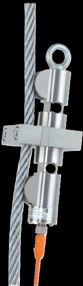
One clamp-on principle, two families
Both clamp onto the installed rope and amplify on board — the family picks the material, the accuracy grade, and the certification.
- rope diameters 6–48 mm; IP66; fixed 3-m cable
- 4–20 mA 2-wire (DC 0–10 V optional)
- ±3% F-nom linearity — overload-protection grade
- breaking force 200% F-nom; CE + EAC
- 1.4542 stainless, ultrasound-tested, 3.1 certificate; IP67
- ≤±1.0% F-nom linearity; breaking force >300% F-nom
- optional redundant 2×4–20 mA output; M12×1 connector
- service temperature to −40°C
- ATEX / IECEx Ex ib IIC T4/T3 Gb; Ex I M2 mining mark (cable connection only)
- 4–20 mA 2-wire only; requires a galvanically isolated supply
- UL 61010-1 / CSA C22.2 No. 61010-1 on the family
Key Features & Benefits
- Retrofit overload protection without touching the rope — the transducer clamps around the installed rope at an anchor point — no opening the rope, no re-reeving, no design changes to the machinery, and, as the datasheet puts it, no new static calculations. An existing hoist gets a tension signal in an afternoon. The measurement comes to the rope, not the rope to the measurement.
- An Ex ib version rated down the mine — the F93C4 carries not just the ATEX/IECEx gas-atmosphere marks but the Group I M2 mining mark — rope tension monitoring on winders and hoists in methane-classified underground work, intrinsically safe by nameplate. The classification travels with the clamp.
- A redundant signal for the safety chain — the F9304 offers a 2×4–20 mA redundant output, so an overload circuit can compare two independent channels off one clamp — the architecture safety reviewers ask for, without a second transducer on the rope. Two opinions from one measurement point.
- Certified steel where the load hangs — the F9304 body is 1.4542 stainless, ultrasound-tested, with a 3.1 material certificate — and a DIN 580 eye bolt plus optional safety chain secure the clamp itself against becoming a dropped object. Paperwork and hardware for gear that hangs over people.
- Sized by rope, not just by load — each rated load maps to a published rope-diameter band (6–48 mm across the F9204 line; two mechanical designs cover 8–44 mm on the F9304), so selection starts from the rope you already have. Two numbers pick the unit: the tension and the rope.
Specifications
- Operating principle
- A force transducer that clamps onto an existing, fully installed steel rope and reads the tension in it — the rope is never opened, cut, or re-terminated, so overload protection retrofits onto a working crane or hoist with no design changes and no new static calculations. Both families carry an integrated amplifier.
- Capacity / measuring range
- F9204: rated loads 1 / 2 / 3.5 / 5 / 10 / 20 / 30–40 t, on rope diameters 6–48 mm. F9304 / F93C4: 0–1 to 0–30 t, on rope diameters 8–44 mm (two mechanical designs, splitting at 25 mm rope).
- Accuracy & repeatability
- F9304 / F93C4: relative linearity error ≤±1.0% Fnom. F9204: ±3% Fnom linearity, ±0.5% repeatability at unchanged mounting (per VDI/VDE/DKD 2638) — the right grade for overload protection rather than precision weighing.
- Output & excitation
- F9204: 4–20 mA 2-wire (DC 0–10 V optional) on a fixed 3-m cable. F9304: 4–20 mA standard with an optional redundant 2×4–20 mA output; F93C4: 4–20 mA 2-wire; both on an M12×1 connector. Reverse-polarity, overvoltage, and short-circuit protected.
- Overload & breaking force
- Force limit 150% Fnom on both families; breaking force 200% Fnom (F9204) / >300% Fnom (F9304 / F93C4).
- Body material
- F9204: alloyed steel. F9304 / F93C4: corrosion-resistant stainless steel 1.4542, ultrasound-tested with a 3.1 material certificate.
- Sealing & protection class
- IP66 (F9204) / IP67 (F9304 / F93C4), per IEC/EN 60529.
- Mounting / load introduction
- Clamps onto the stationary rope in a few steps at a rope anchor point; the F9304 family adds a DIN 580 eye bolt and an optional 1-m safety chain, with published clamp-bolt torques (20 / 46 N·m by design).
- Temperature range
- F9204: rated −10 to +60°C, operating −20 to +80°C. F9304: rated −20 to +80°C, service −40 to +80°C.
- Thermal effect
- On zero and on characteristic value: ≤±0.25%/10 K (F9204); 0.2%/10 K (F9304 / F93C4).
- Approvals & options
- F93C4 is the intrinsically-safe variant: ATEX / IECEx Ex ib IIC T4/T3 Gb gas marks and the Ex I M2 Ex ib I Mb mining mark (cable connection only), plus UL 61010-1 / CSA C22.2 No. 61010-1 on the family. F9204 carries CE + EAC. Vibration-tested 20 g, 100 h (DIN EN 60068-2-6, F9304 family).
- Build & lead time
- Configured per the rated load, the rope diameter band, the output, and the area classification. Quote-only, no public price list.
Common Applications
- Overload protection of cranes and storage-and-retrieval machines
- Rope-tension measurement and monitoring on hoists and winches
- Retrofitting a load signal onto existing lifting equipment — no design changes or new static calculations
- Classified-area rope monitoring — gas atmospheres and Group I mining (F93C4)
Design & Selection Considerations
- The rope is part of the calibration — a clamp-on transducer reads tension through the rope’s own stiffness, so the lay, diameter, and condition of the rope influence the signal — the datasheets specify repeatability at unchanged mounting position for exactly this reason. Calibrate in place against a known load where the accuracy matters, and re-check after the rope is changed. Same clamp + new rope = new zero.
- Pick the family by duty, not just price — the F9204’s ±3% linearity is honest overload-protection grade; the F9304’s ≤±1.0% in certified stainless is the pick where the number feeds a displayed load, a logged record, or a classified area (F93C4). Trip-point duty and measurement duty are different specs.
- Mount at a stationary anchor point — the transducer belongs on the dead (stationary) rope at an anchor point — not on a rope section that runs over sheaves — and the F9304’s published clamp torques (20 / 46 N·m by design) are part of the measurement. Where and how tight are both spec lines.
- Get the load axial, centered, and free of side load — these transducers measure force introduced straight down their axis. Take an off-center or transverse load and the reading is wrong and the element can be damaged — the datasheets call for a load that is axial, centric, and free of transverse force and torque. Most field errors here are load-introduction errors, not sensor errors.
- Size so the working load lands in the upper part of the range — aim to put the routine working load high enough in the range for good resolution and signal-to-noise, with headroom for peaks. Oversize and resolution suffers; undersize and an overload event shifts the calibration. Use the input form to tell us the static load and the worst-case peak — not just the nominal.
- Know the gap between safe overload and breaking force — every unit has a safe overload it can see without losing calibration and a higher breaking force where it is destroyed. The danger zone is between them: a unit overloaded past safe but not to breaking keeps reporting plausible, wrong numbers. Any suspected overload should trigger a recalibration before you trust the data again.
- Watch cross-sensitivity where the load can swing off-axis — a side load produces a real, specified error (the F5301, for example, carries a cross-sensitivity rating for load applied at 90°). Where the loading geometry can move — a swinging sheave, a misaligned fixture — account for it in the error budget or constrain the geometry. Off-axis load is a spec line for a reason.
- Pick the output to match what is reading the sensor — a raw mV/V bridge needs a conditioning input (DAQ or indicator with a bridge card); an integrated or cable amplifier reads straight into a PLC as 4–20 mA or 0–10 V. Use 4–20 mA for long, noisy runs; 0–10 V for short test-bench runs. Decide it from the receiver and the cable distance.
- A legacy tecsis part number cross-references to a current WIKA-ST unit — the tecsis force line is now built under WIKA Sensor Technology. Use the input form to send the tecsis part number and we match the current WIKA-ST equivalent at the same spec, so a field replacement does not require re-engineering the installation. No need to re-spec from scratch on a like-for-like swap.
To spec the right WIKA-ST wire-rope tension cell:
To configure the right WIKA-ST force sensor, have these ready: the capacity (and the worst-case peak load); whether the force is tension, compression, or both; how the load is introduced (through an existing pin, a ring in the force path, or a threaded line); the output you need (4–20 mA, 0–10 V, mV/V, CANopen, or wireless) and the cable run; the environment (temperature, washdown, classified area); any certification (ATEX/IECEx, functional safety); and, for a load pin, the existing pin dimensions to match. A legacy tecsis part number is fine — send it and we cross-reference the current WIKA-ST equivalent.
Force & Pressure Application Sheet ›Talk to an engineer directly — Scott Prater, Principal · 917-580-0878 · scott@pratertechnical.com
Specifications compiled by Prater Technical Partners from WIKA product datasheets.