Product Overview
WIKA-ST embedded strain sensors retrofit force measurement onto structures that cannot take a load cell: instead of breaking the force path, a thin-film bridge reads the microstrain of the member itself and an integrated amplifier makes it a standard signal. The F9302 strain link bolts on with two M6 screws (200 / 500 / 1,000 µε ranges, 4–20 mA, PLC-tared) — the pick for presses, structural steel, special vehicles, and vessel supports. The F9303 / F93C3 press-in sensor disappears into a Ø20 H7 bore and answers in ≤1 ms — the OEM’s embedded option for machine automation, container weighing, and crane structures. Both calibrate on your structure, because your structure is the spring.
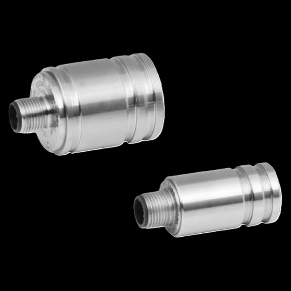
Bolt-on or press-in — two ways onto the structure
Both read structural microstrain through a thin-film bridge with an integrated amplifier; the variant picks the attachment and the electronics.
- ranges 0–±200 / ±500 / ±1,000 µε
- 4–20 mA 3-wire with PLC-driven “Tara” zeroing
- two M6 screws at 12 N·m; removable and refittable (0.5% repeatability after refitting)
- current sheet FO 54.10 (03/2026), M12×1 connector
- for members straining 0.1–0.25‰, steel >350 N/mm², wall ≥4 mm
- 4–20 mA 2-wire or 0–10 V 3-wire; response ≤1 ms
- zero/span set in place with the EPE01 handheld unit
- pressed in at up to 30 kN — never hammered
- same press-fit body and outputs as the F9303
- service temperature −25 to +80°C (vs −40°C standard)
Key Features & Benefits
- The machine member becomes the load cell — nothing is inserted into the force path, no joint is opened, and the structure’s strength is untouched — the sensor reads the strain the member already sees. Press-fit or two M6 screws retrofit force measurement onto presses, cranes, and vessel supports that were never designed for a transducer. Force measurement where a load cell will never fit.
- Thin-film without the adhesive problem — the element is a sputtered thin-film bridge, not a glued foil gauge — the datasheet point is that it keeps the advantages of a conventional strain gauge while eliminating the adhesive’s temperature response and creep, which is what usually limits a permanently installed structural gauge. Built for years on the structure, not a test campaign.
- Zeroed from the PLC, in place — the F9302’s Tara control line lets the controller re-zero the installed sensor by bit sequence — tooling changes, dead loads, and drift get tared out without anyone climbing to the sensor with a screwdriver. Maintenance is a line of ladder logic.
- Millisecond response for press and stamping control — the press-in F9303 responds in ≤1 ms with its amplifier on board — fast enough to ride the force curve of an injection-molding, stamping, or embossing stroke, cycle after cycle. In-cycle force, not an after-the-fact log.
- Repeatable even after refitting — the F9302 specifies 0.5% repeatability not only at unchanged mounting but after remounting at a different position — the spec that makes a bolt-on structural sensor serviceable rather than a one-shot installation. Take it off, put it back, trust it again.
Specifications
- Operating principle
- Instead of putting a load cell in the force path, an embedded strain sensor turns the machine’s own structure into the transducer: a 7-mm thin-film element with a temperature-compensated Wheatstone bridge reads the microstrain of the member it is fixed to, and an integrated digital amplifier turns it into a standard signal. The F9302 bolts on; the F9303 / F93C3 presses into a bore.
- Capacity / measuring range
- F9302: strain ranges 0–±200, ±500, or ±1,000 µε (structures straining to max. 1.0‰). F9303 / F93C3: structures straining 0.1–0.25‰ with tensile strength >350 N/mm²; limit elongation 150% εnom. The force reading is whatever that strain means in your member — set at calibration.
- Accuracy & repeatability
- F9302: relative linearity error ≤±2% Fnom, repeatability 0.5% Fnom — both at unchanged AND at different mounting positions. F9303: combined error ≤±2% of full scale, hysteresis ≤±0.5%, creep <0.5%/30 min — each “depending on installation,” because the structure is part of the measurement.
- Output & excitation
- F9302: 4–20 mA 3-wire, with a “Tara” control line — the PLC zeroes the sensor in place by bit sequence. F9303 / F93C3: 4–20 mA 2-wire or 0–10 V 3-wire, response time ≤1 ms, zero and span set after installation with the EPE01 handheld programming unit.
- Body material
- Stainless steel (F9302 measuring element: 1.4542).
- Sealing & protection class
- IP67 on both families (IEC/EN 60529).
- Dimensions / fit
- F9302: 84 × 38 × 25 mm, 200 g, screw spacing 66 mm. F9303: a 36-mm body pressed into a Ø20 H7 bore in material ≥4 mm thick.
- Mounting / load introduction
- F9302: two captive M6 screws (DIN EN ISO 4762 M6×16-10.9) torqued to 12 N·m onto a surface prepared to 0.05 mm evenness / Ra 16. F9303: pressed in — never hammered — at up to 30 kN press force, with the alignment notch oriented to the strain direction.
- Temperature range
- Rated −20 to +80°C on both; F9302 operates −40 to +80°C (permanently laid cable); F9303 service range −40 to +80°C (F93C3: −25 to +80°C); storage to +85°C.
- Thermal effect
- F9302: zero 0.1%/10 K, characteristic value 0.3%/10 K. F9303: typ. ±0.5% εnom/10 K on zero and span, depending on the material pairing.
- Approvals & options
- EMC per DIN EN 55011 / 61326-1 / 61326-2-3; vibration-tested 20 g, 100 h, 50–150 Hz (DIN EN 60068-2-6); reverse-polarity, overvoltage, and short-circuit protected. Specified per VDI/VDE/DKD 2638 (F9302).
- Calibration & traceability
- The sensor ships factory-preset; the force calibration happens on your structure — zero in the unloaded state (F9302: via the Tara line; F9303: via the EPE01 handheld), then span against a known load. Overall accuracy is quoted “depending on installation” for exactly this reason.
- Build & lead time
- Configured per the strain range, output, and connection (F9302: M12×1 4-pin, 10-m molded-cable option). Quote-only, no public price list.
Common Applications
- Injection molding machines — clamp and injection force off the frame
- Presses, stamping and embossing machines — in-cycle force monitoring
- Structural steelwork and vessel supports
- Special vehicles and construction machines
- Hoists, cranes, and container weighing (press-in F9303)
- Manufacturing automation and fill-level control on machine structures
Design & Selection Considerations
- The accuracy is a system number, not a sensor number — both datasheets quote overall accuracy “depending on installation” — the stiffness, material, and strain level of your member set what ±2% actually means in force. Plan an in-situ calibration against a known load, and treat the published figure as the sensor’s contribution. You are calibrating a structure, and the sensor is along for the ride.
- Put it where the strain is — the sensor must sit at a location that strains measurably and repeatably with the load — the F9302 needs the member working below 1.0‰ elongation, the F9303 wants 0.1–0.25‰ in steel above 350 N/mm². A stiff corner that never strains reads nothing; a joint that shifts reads noise. Placement is an engineering decision — send us the structure drawing.
- Surface prep and press-fit rules are part of the spec — the F9302 requires 0.05-mm evenness and Ra 16 under its feet with 12 N·m on each screw; the F9303 must be pressed — the sheet says plainly, do not bang it in — with the notch aligned. Shortcut the install and the calibration will not repeat. The torque wrench is a measuring instrument here.
- Mind the F9303’s narrower Ex-variant temperature window — the F93C3 serves −25 to +80°C where the standard F9303 reaches −40°C — if the install is an outdoor crane structure in a cold climate, check which variant the environment actually allows. The certification and the climate must both fit.
- Get the load axial, centered, and free of side load — these transducers measure force introduced straight down their axis. Take an off-center or transverse load and the reading is wrong and the element can be damaged — the datasheets call for a load that is axial, centric, and free of transverse force and torque. Most field errors here are load-introduction errors, not sensor errors.
- Size so the working load lands in the upper part of the range — aim to put the routine working load high enough in the range for good resolution and signal-to-noise, with headroom for peaks. Oversize and resolution suffers; undersize and an overload event shifts the calibration. Use the input form to tell us the static load and the worst-case peak — not just the nominal.
- Know the gap between safe overload and breaking force — every unit has a safe overload it can see without losing calibration and a higher breaking force where it is destroyed. The danger zone is between them: a unit overloaded past safe but not to breaking keeps reporting plausible, wrong numbers. Any suspected overload should trigger a recalibration before you trust the data again.
- Watch cross-sensitivity where the load can swing off-axis — a side load produces a real, specified error (the F5301, for example, carries a cross-sensitivity rating for load applied at 90°). Where the loading geometry can move — a swinging sheave, a misaligned fixture — account for it in the error budget or constrain the geometry. Off-axis load is a spec line for a reason.
- Pick the output to match what is reading the sensor — a raw mV/V bridge needs a conditioning input (DAQ or indicator with a bridge card); an integrated or cable amplifier reads straight into a PLC as 4–20 mA or 0–10 V. Use 4–20 mA for long, noisy runs; 0–10 V for short test-bench runs. Decide it from the receiver and the cable distance.
- A legacy tecsis part number cross-references to a current WIKA-ST unit — the tecsis force line is now built under WIKA Sensor Technology. Use the input form to send the tecsis part number and we match the current WIKA-ST equivalent at the same spec, so a field replacement does not require re-engineering the installation. No need to re-spec from scratch on a like-for-like swap.
To spec the right WIKA-ST embedded strain sensor:
To configure the right WIKA-ST force sensor, have these ready: the capacity (and the worst-case peak load); whether the force is tension, compression, or both; how the load is introduced (through an existing pin, a ring in the force path, or a threaded line); the output you need (4–20 mA, 0–10 V, mV/V, CANopen, or wireless) and the cable run; the environment (temperature, washdown, classified area); any certification (ATEX/IECEx, functional safety); and, for a load pin, the existing pin dimensions to match. A legacy tecsis part number is fine — send it and we cross-reference the current WIKA-ST equivalent.
Force & Pressure Application Sheet ›Talk to an engineer directly — Scott Prater, Principal · 917-580-0878 · scott@pratertechnical.com
Specifications compiled by Prater Technical Partners from WIKA product datasheets.