Product Overview
The tecsis XLWP pillow-block load cell (now WIKA Sensor Technology) measures the force on a rotating shaft through its own bearing block: 10 to 50 kN of bearing reaction read at 0.5% combined accuracy, in stainless steel sealed to IP69K, with a 6-wire sense-corrected mV/V bridge. It comes from the tecsis custom-and-industry-specific solutions line — the answer when a roller, web, or shaft load must be measured and there is no room in the shaft line for anything else. Published at catalog depth; the full drawing (99-3240-0000) and shaft-fit detail come with the quote.
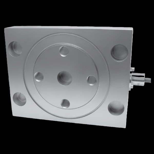
Key Features & Benefits
- The bearing block IS the sensor — web tension, roller nip load, and shaft force usually mean redesigning the machine frame to insert a cell — the XLWP instead replaces the pillow block the shaft already needs, reading the bearing reaction directly. Force measurement that bolts where a bearing housing already bolts.
- IP69K where the shaft gets hosed down — the highest washdown rating in the IEC scheme, in stainless — a live-shaft force measurement that survives the caustic rinse in food, converting, and process lines. Wash the machine, keep the measurement.
- Six wires, honest signal — sense leads let the readout correct for excitation drop over a long cable run — a real factor on a cell that lives out on the machine frame far from the panel. The bridge sees the excitation you think it sees.
- Hot-running duty to +149°C — operating temperature reaches 149°C with a compensated band to +140°C — dryer sections, heated calendars, and process rolls run inside its envelope, not past it. Rated for the roll that runs hot.
- Overload margins for a shaft that misbehaves — safe overload at 150% and ultimate at 300% FSO, with the cell fully temperature-compensated across its +20 to +140°C band — a wrapped web, a jammed roll, or a thermal excursion stays inside the ratings instead of ending the measurement. Margin where the process is the hazard.
Specifications
- Operating principle
- A strain-gauge load cell built as a pillow-block (bearing-block) housing — the shaft’s bearing sits on the cell, so the bearing reaction force is measured continuously without adding anything to the shaft line. The catalog files it under “custom & industry-specific solutions”: a sensor shaped to the fixturing instead of fixturing redesigned around a sensor.
- Capacity / measuring range
- 0–10 / 20 / 30 / 50 kN (ordering codes 99-3240-10kN through 99-3240-50kN).
- Accuracy & repeatability
- Linearity + hysteresis 0.5% FSO combined.
- Output & excitation
- 1.95 mV/V ±0.5% on a 700-Ω bridge; excitation 10 VDC (15 VDC max); 6-wire connection with sense leads for long-run excitation correction.
- Overload & breaking force
- Safe overload 150% FSO; ultimate 300% FSO.
- Body material
- Stainless steel.
- Sealing & protection class
- IP69K — washdown-rated.
- Dimensions / fit
- ~205 × 160 mm footprint; base mounts on 4× Ø17-mm counterbored through-holes with an M16×1.5 threaded feature; load axes marked X/Y on the drawing. Also available dimensioned in American units.
- Mounting / load introduction
- Bolts down like a pillow-block bearing housing; the measured member is the shaft load passing through the bearing seat.
- Temperature range
- Operating −10 to +149°C; compensated +20 to +140°C.
- Thermal effect
- Zero ±0.009% FSO/°C; span ±0.009% of reading/°C.
- Build & lead time
- Published at catalog-page depth — the full drawing and current ordering detail come back with the quote. As a custom-solutions line item, shaft fit and variant details are confirmed per application. Quote-only, no public price list.
Common Applications
- Shaft and roller load measurement through the bearing block
- Web-handling and converting lines — nip and wrap force on live shafts
- Washdown environments where an IP69K-rated cell must live on the frame
- Custom force-measurement fits — the sensor shaped to the fixturing
Design & Selection Considerations
- Catalog depth — confirm the fit at quote — the XLWP is published as a catalog solutions page, not a full datasheet: shaft/bearing fitment, cable detail, and current variants are confirmed per application. Use the input form to send the shaft diameter, bearing, and load direction with the inquiry. Treat this page as selection, not specification.
- Mind the load direction the block was calibrated for — the drawing defines X and Y load axes — a pillow-block cell reads the bearing reaction along its calibrated axis, and a load that swings between axes needs to be resolved in the application review. Use the input form to tell us which way the shaft pulls, through the whole duty cycle.
- The readout needs a bridge input — output is raw mV/V — plan a conditioned input (indicator, DAQ bridge card, or an amplifier from the displays & amplifiers group) and use the 6-wire sense connection on long runs. Budget the electronics with the cell.
- Get the load axial, centered, and free of side load — these transducers measure force introduced straight down their axis. Take an off-center or transverse load and the reading is wrong and the element can be damaged — the datasheets call for a load that is axial, centric, and free of transverse force and torque. Most field errors here are load-introduction errors, not sensor errors.
- Size so the working load lands in the upper part of the range — aim to put the routine working load high enough in the range for good resolution and signal-to-noise, with headroom for peaks. Oversize and resolution suffers; undersize and an overload event shifts the calibration. Use the input form to tell us the static load and the worst-case peak — not just the nominal.
- Know the gap between safe overload and breaking force — every unit has a safe overload it can see without losing calibration and a higher breaking force where it is destroyed. The danger zone is between them: a unit overloaded past safe but not to breaking keeps reporting plausible, wrong numbers. Any suspected overload should trigger a recalibration before you trust the data again.
- Watch cross-sensitivity where the load can swing off-axis — a side load produces a real, specified error (the F5301, for example, carries a cross-sensitivity rating for load applied at 90°). Where the loading geometry can move — a swinging sheave, a misaligned fixture — account for it in the error budget or constrain the geometry. Off-axis load is a spec line for a reason.
- Pick the output to match what is reading the sensor — a raw mV/V bridge needs a conditioning input (DAQ or indicator with a bridge card); an integrated or cable amplifier reads straight into a PLC as 4–20 mA or 0–10 V. Use 4–20 mA for long, noisy runs; 0–10 V for short test-bench runs. Decide it from the receiver and the cable distance.
- A legacy tecsis part number cross-references to a current WIKA-ST unit — the tecsis force line is now built under WIKA Sensor Technology. Use the input form to send the tecsis part number and we match the current WIKA-ST equivalent at the same spec, so a field replacement does not require re-engineering the installation. No need to re-spec from scratch on a like-for-like swap.
To spec the right WIKA-ST pillow-block load cell:
To configure the right WIKA-ST force sensor, have these ready: the capacity (and the worst-case peak load); whether the force is tension, compression, or both; how the load is introduced (through an existing pin, a ring in the force path, or a threaded line); the output you need (4–20 mA, 0–10 V, mV/V, CANopen, or wireless) and the cable run; the environment (temperature, washdown, classified area); any certification (ATEX/IECEx, functional safety); and, for a load pin, the existing pin dimensions to match. A legacy tecsis part number is fine — send it and we cross-reference the current WIKA-ST equivalent.
Force & Pressure Application Sheet ›Talk to an engineer directly — Scott Prater, Principal · 917-580-0878 · scott@pratertechnical.com
Specifications compiled by Prater Technical Partners from WIKA product datasheets.