Product Overview
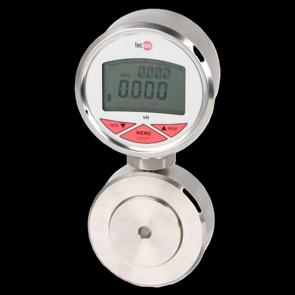
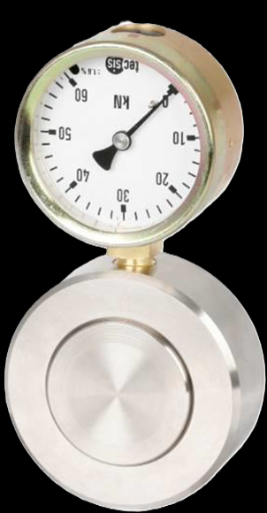
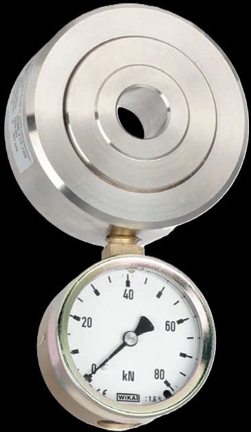
WIKA-ST hydraulic force transducers measure force the pre-electronic way, done to current datasheet grade: the load presses a piston against a sealed glycerine/water fill, and a pressure gauge reads the result directly in force units — no supply voltage anywhere in the measurement. The F1106 compression transducer covers 160 N to 60 kN; the F6116 and F6154 rings put a through-hole around a rod or anchor to 120 and 1,500 kN; and the F6137 / F6148 / F6160 / F6171 geotechnical rings hold 80 kN to 6,000 kN on anchor heads for continuous monitoring in tunnel, mining, and slope-stabilisation work — with a 4–20 mA option where a control room wants the number too. Static and quasi-static duty; digital readout tightens accuracy to ±0.5% Fnom.
Key Features & Benefits
- Force measurement with no power supply at all — the piston-and-fill principle needs no excitation, no amplifier, and no cable run — the pressure gauge on the cell IS the readout. That puts a trustworthy force number on an anchor head in a tunnel, a jig in a fixture shop, or a bracing rod on a slope where nobody is running power. The reading is there when the electrician is not.
- A 5-year leak-tightness warranty on a sealed hydraulic system — the closed fill is the measuring element, so WIKA warrants it as one: an industrial unit that starts to leak within five years is repaired free of charge. The failure mode that matters is the one under warranty.
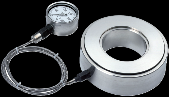
- Swap the display without opening the system — ordered with a capillary or DN 2 measuring hose, the display separates from the transducer with no fluid loss — the geotechnical versions explicitly allow the readout to be disconnected and replaced under operating conditions, while the anchor stays loaded and monitored. Maintenance without unloading the anchor.
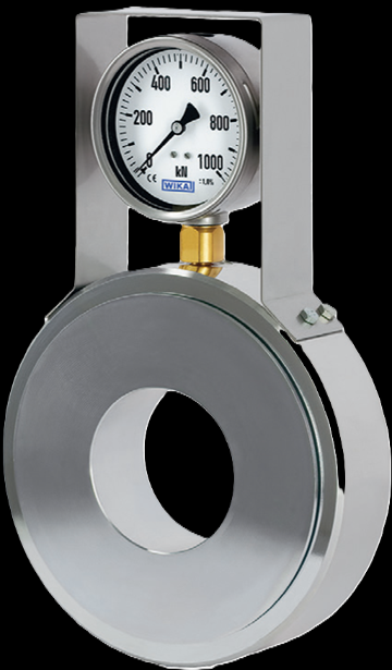
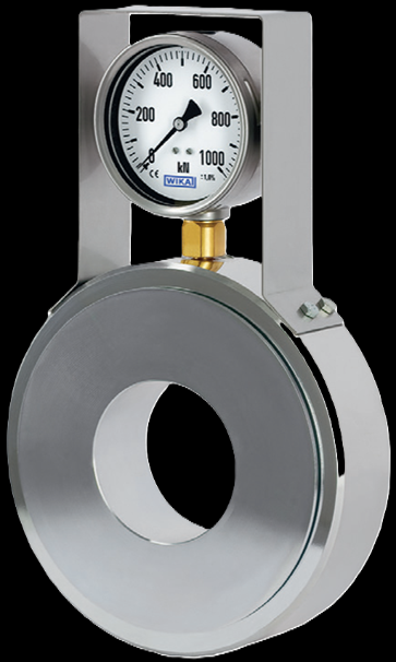
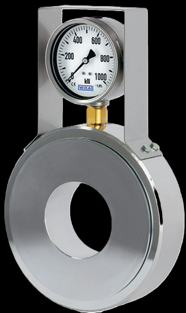
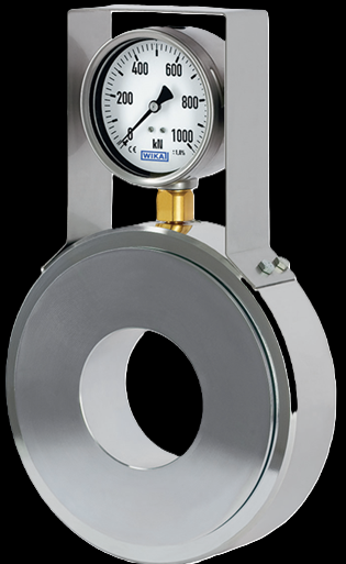
- Built for the anchor head, not the lab — the geotechnical rings put a galvanised-steel cylinder-piston set directly at the anchor head with a guard bracket over the gauge, reading 80 kN to 6,000 kN of clamping force through years of continuous anchor and bracing-rod monitoring in tunnel, mining, and retaining-wall work. A force gauge that lives outdoors on structural steel.
- One principle from 160 N to 6,000 kN — the same hydraulic measurement scales from a 160-N bench transducer to a 6,000-kN anchor ring — compression button, compact ring, heavy-duty ring, and geotechnical ring are one selection ladder, not four technologies to learn. Pick the form, then the range.
Specifications
- Operating principle
- A hydraulic piston instead of a strain gauge: force on the piston raises the pressure of a sealed glycerine/water fill in proportion (force = area × pressure), and a connected pressure instrument displays it directly in N, kN, kg, or t. The measuring unit operates without any supply voltage — force readout where there is no power at all.
- Capacity / measuring range
- F1106 compression: 0–160 N to 0–60 kN (17 rated forces). F6116 compact ring: 0–320 N to 0–120 kN. F6154 heavy-duty ring: 0–25 to 0–1,500 kN. Geotechnical rings: F6137 to 700 kN, F6148 to 1,500 kN, F6160 to 3,200 kN, F6171 to 6,000 kN (1,348,854 lbf).
WIKA-ST hydraulic force transducers — version selector
| Model | Version | Rated forces | Analog accuracy | Temperature range |
|---|---|---|---|---|
| F1106 | Compression, compact (NS 10) | 160 N – 60 kN | ≤±1.6% F-nom | −25 … +50°C |
| F6116 | Ring, compact (NS 20) | 320 N – 120 kN | ≤±1.6% F-nom | −25 … +50°C |
| F6154 | Ring, heavy-duty (NS 240) | 25 – 1,500 kN | ≤±1.6% F-nom | −25 … +90°C |
| F6137 | Ring, geotechnical (NS 82) | 80 – 700 kN | ≤±1.0% F-nom | −30 … +60°C |
| F6148 | Ring, geotechnical (NS 146) | 150 – 1,500 kN | ≤±1.0% F-nom | −30 … +60°C |
| F6160 | Ring, geotechnical (NS 383) | 400 – 3,200 kN | ≤±1.0% F-nom | −30 … +60°C |
| F6171 | Ring, geotechnical (NS 383) | 800 – 6,000 kN | ≤±1.0% F-nom | −30 … +60°C |
- Accuracy & repeatability
- Set by the readout: ≤±0.5% Fnom with the DG-10 digital gauge or a pressure sensor; ≤±1.6% Fnom with the standard analog gauge on the industrial models; the geotechnical versions read ≤±1.0% Fnom on their larger NS 100 analog gauge.
- Output & excitation
- Standard readout is a mounted analog pressure gauge (model 213.40 NS 63 industrial; 23x.50 NS 100 geotechnical); options include a gauge with switch contacts (PGS23), the DG-10 digital gauge, and a pressure sensor. The geotechnical models offer a 4–20 mA 2-wire output over an M12×1 connector for remote anchor monitoring.
- Overload & breaking force
- Force limit 100% Fnom; breaking force >130% Fnom — a hydraulic transducer has no overload headroom above its rated force, so the worst-case load must sit inside the range.
- Body material
- Industrial models (F1106 / F6116 / F6154): stainless-steel case and piston. Geotechnical models: electrogalvanised steel case and piston, with a stainless option. Fill fluid: glycerine 70% / water 30%.
- Sealing & protection class
- IP65 with the analog gauge; IP67 with the pressure sensor (per IEC/EN 60529).
- Dimensions / fit
- Piston stroke ≤0.5 mm (F6154: ≤0.8 mm) — the reading costs almost no travel in the force path. Weights run from 1.2 kg (F1106 with gauge) to 122 kg (F6171).
- Mounting / load introduction
- Direct mounting or adapter; a capillary line or DN 2 measuring hose separates the display from the transducer without fluid loss, so the instrument can be exchanged — on the geotechnical anchor systems, disconnected and replaced under operating conditions — without dismounting the cell. Force introduction as full-faced as possible (min. 75% of the piston diameter on the geotechnical rings).
- Temperature range
- F1106 / F6116: −25 to +50°C. F6154: −25 to +90°C. Geotechnical models: −30 to +60°C.
- Approvals & options
- CE (EU declaration of conformity, EMC + RoHS); EAC option. Specified per VDI/VDE/DKD 2638. The industrial models carry WIKA’s 5-year leak-tightness warranty — a transducer that starts to leak within the period is repaired free of charge.
- Build & lead time
- Configured per the rated force, readout instrument, and connection (direct / capillary / measuring hose, lengths to 3.2 m; longer on request). Quote-only, no public price list.
Common Applications
- Continuous anchor and bracing-rod monitoring — tunnel construction, mining (surface and underground), bridge building, slope stabilisation, retaining walls and excavations
- Equipment manufacturing and special machine building
- Construction of jigs and fixtures — clamping-force verification
- Measuring and control systems where no supply voltage is available
- Geotechnology and specialist foundation engineering (heavy-duty ring)
Design & Selection Considerations
- The closed system must never be opened — transducer, fill, and display are one factory-sealed measuring unit — disconnecting a coupling destroys the measuring function and voids the warranty. Order the capillary or measuring-hose separation if you will ever need to service the display. Decide the maintenance path at order time, not with a wrench.
- Rated force IS the limit force — size with real headroom — unlike a strain-gauge cell with 150% safe overload, the hydraulic models specify the force limit at 100% of rated force and breaking above 130%. The worst-case load, not the working load, picks the range. There is no overload cushion to lean on.
- Static and quasi-static duty only — the piston-and-fill system is made for loads that hold or change slowly — anchor tension, jig clamping, test-fixture force. For cyclic or fast-changing loads, use a strain-gauge transducer with a fatigue rating instead. Match the physics to the duty cycle.
- The readout choice sets the accuracy class — the same transducer reads ≤±1.6% F-nom on the standard analog gauge, ≤±1.0% on the geotechnical NS 100 gauge, and ≤±0.5% with the digital gauge or pressure sensor — decide what accuracy the application actually needs before paying for it, or under-buying it. Accuracy lives in the instrument, not the cylinder.
- Get the load axial, centered, and free of side load — these transducers measure force introduced straight down their axis. Take an off-center or transverse load and the reading is wrong and the element can be damaged — the datasheets call for a load that is axial, centric, and free of transverse force and torque. Most field errors here are load-introduction errors, not sensor errors.
- Size so the working load lands in the upper part of the range — aim to put the routine working load high enough in the range for good resolution and signal-to-noise, with headroom for peaks. Oversize and resolution suffers; undersize and an overload event shifts the calibration. Use the input form to tell us the static load and the worst-case peak — not just the nominal.
- Know the gap between safe overload and breaking force — every unit has a safe overload it can see without losing calibration and a higher breaking force where it is destroyed. The danger zone is between them: a unit overloaded past safe but not to breaking keeps reporting plausible, wrong numbers. Any suspected overload should trigger a recalibration before you trust the data again.
- Watch cross-sensitivity where the load can swing off-axis — a side load produces a real, specified error (the F5301, for example, carries a cross-sensitivity rating for load applied at 90°). Where the loading geometry can move — a swinging sheave, a misaligned fixture — account for it in the error budget or constrain the geometry. Off-axis load is a spec line for a reason.
- Pick the output to match what is reading the sensor — a raw mV/V bridge needs a conditioning input (DAQ or indicator with a bridge card); an integrated or cable amplifier reads straight into a PLC as 4–20 mA or 0–10 V. Use 4–20 mA for long, noisy runs; 0–10 V for short test-bench runs. Decide it from the receiver and the cable distance.
- A legacy tecsis part number cross-references to a current WIKA-ST unit — the tecsis force line is now built under WIKA Sensor Technology. Use the input form to send the tecsis part number and we match the current WIKA-ST equivalent at the same spec, so a field replacement does not require re-engineering the installation. No need to re-spec from scratch on a like-for-like swap.
To spec the right WIKA-ST hydraulic force transducer:
To configure the right WIKA-ST force sensor, have these ready: the capacity (and the worst-case peak load); whether the force is tension, compression, or both; how the load is introduced (through an existing pin, a ring in the force path, or a threaded line); the output you need (4–20 mA, 0–10 V, mV/V, CANopen, or wireless) and the cable run; the environment (temperature, washdown, classified area); any certification (ATEX/IECEx, functional safety); and, for a load pin, the existing pin dimensions to match. A legacy tecsis part number is fine — send it and we cross-reference the current WIKA-ST equivalent.
Force & Pressure Application Sheet ›Talk to an engineer directly — Scott Prater, Principal · 917-580-0878 · scott@pratertechnical.com
Specifications compiled by Prater Technical Partners from WIKA product datasheets.