Product Overview
The WIKA-ST XPMF is the miniature flush-diaphragm pressure transducer: the sensing diaphragm sits flat at the process face, so there is no tapped port cavity to trap viscous or curing media, entrain gas, or dead-volume a fast pressure. Three builds share the flush face and the 17-4 PH stainless body — the subminiature XPMF03 on cable leads, to 0–20,000 psi; the rugged XPMF04 with a military connector and a 7/16-20 O-ring face; and the XPMF05 with the same connector on a 1/4-NPT thread, both to 15,000 psi. Bonded-foil bridge, 2 mV/V output (a low-range mV/psi option on the 04 / 05), −65 to +300°F, 150% safe overpressure. Have a legacy tecsis part number for this measurement? Send it — WIKA acquired tecsis and now ships these under WIKA Sensor Technology, and we cross-reference the tecsis p/n to the current WIKA-ST equivalent at the same spec.
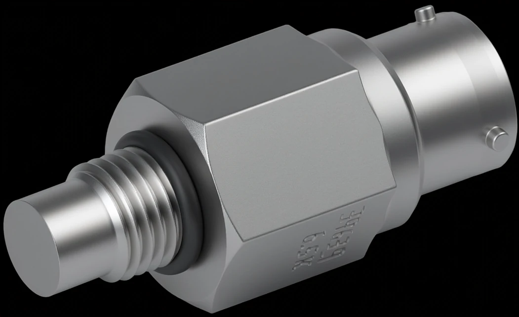
One flush-diaphragm family, three sizes and terminations
All three share the flush diaphragm, the 17-4 PH stainless construction, the bonded-foil 350 Ω bridge at 5 VDC, the −65 to +300°F range, and 150% safe overpressure — the model picks the size, the seal, and the termination.
- smallest body; twisted Teflon flying leads (2–3 ft)
- 3/8-24 or 7/16-20 UNF flush face, O-ring (011 / 012)
- 2 mV/V; combined linearity+hysteresis ±1.0% FSO
- rugged welded body, 3/4 hex; military-type PTIH-10-6P connector
- 7/16-20 UNF flush face, O-ring (012)
- 2 mV/V above 100 psi or 0.1 mV/psi at ≤100 psi; ±0.50% combined
- same connector and output as the 04, on a 1/4-18 NPT thread
- welded stainless, 3/4 hex; no O-ring (tapered pipe seal)
- 2 mV/V above 100 psi or 0.1 mV/psi at ≤100 psi; ±0.50% combined
Key Features & Benefits
- The diaphragm is the process face — nothing to trap or dead-volume — a flush diaphragm sits flat at the port, so there is no tapped cavity to hold viscous or curing media, entrain gas, or slow a fast pressure with a column of trapped fluid. The build for mold cavities, manifolds, and anything that would clog an ordinary port.
- Miniature envelope, 20,000 psi capability — a subminiature 03 body threads into tight tooling where a full-size transducer will not fit, and still reaches 20,000 psi full scale; the rugged 04 / 05 take the same flush face to 15,000 psi with a welded stainless body. Small where it has to be, without giving up range.
- A wide operating band for hot tooling — a −65 to +300°F operating range and 17-4 PH stainless construction let the flush face sit close to hot molds and manifolds where a cabled sensor would cook. Built to live at the process, not near it.
Specifications
- Sensing principle
- Bonded-foil strain gauge on a flush diaphragm at the process face — no tapped port cavity to trap media, entrain gas, or dead-volume a fast pressure. 350 Ω bridge, 5 VDC excitation.
- Pressure type
- Gauge / sealed reference (the sheets code the range with a trailing S).
- Measuring range
- XPMF03: 0–150 to 0–20,000 psi. XPMF04 & XPMF05: 0–15 to 0–15,000 psi.
- Accuracy
- Combined linearity and hysteresis ±0.50% FSO on the 04 and 05, ±1.0% FSO on the subminiature 03; repeatability ±0.10% FSO; zero balance ±3.0% FSO.
- Thermal effects
- ±0.01% FSO/°F on zero and ±0.02% reading/°F on span, across all three.
- Output signal
- XPMF03: 2 mV/V. XPMF04 & XPMF05: 2 mV/V above 100 psi, or 0.1 mV/psi (at 5 VDC) on ranges of 100 psi and below.
- Excitation / supply
- 5 VDC; bridge resistance 350 Ω.
- Electrical connection
- XPMF03: twisted Teflon flying leads (2–3 ft). XPMF04 & XPMF05: Bendix PTIH-10-6P (or equal) military-type connector.
- Wetted parts material
- 17-4 PH stainless steel, welded stainless construction (04 / 05).
- Process connection
- XPMF03: 3/8-24 UNF or 7/16-20 UNF, flush face, O-ring seal (size 011 / 012). XPMF04: 7/16-20 UNF, flush face, O-ring (012), 3/4 hex. XPMF05: 1/4-18 NPT, 3/4 hex.
- Overpressure / proof
- Safe overpressure 150% of capacity.
- Operating temperature
- −65 to +300°F (−54 to +150°C).
- Compensated temperature
- +60 to +160°F (+15 to +71°C).
- Approvals & certification
- Supplied with the mating O-ring (03 / 04). Also available in metric units.
- Configuration & lead time
- Configured per the range, the size / thread, and the termination. Quote-only, no public price list.
Common Applications
- Injection-mold cavity and runner pressure
- Hydraulic manifold and point-of-injection pressure with no dead volume
- Tight-envelope OEM and test-fixture pressure to 20,000 psi
- Viscous, curing, or slurry media that would clog a tapped port
Design & Selection Considerations
- Match the mounting thread and O-ring to the tooling, not just the range — the three builds differ mainly in how they seal: the 03 and 04 use a straight UNF thread with a flush O-ring face (a machined counterbore in your part), while the 05 uses a 1/4-NPT tapered thread. Confirm the port the tooling can accept before the range — a flush O-ring face needs a matching counterbore that an NPT tap will not give you. The seal design, not the pressure, usually picks the model.
- The datasheet quotes combined linearity + hysteresis, not a single accuracy — the XPMF sheets print a combined linearity-and-hysteresis figure rather than a separated accuracy spec. When you compare it to a sensor that quotes linearity alone, you are not comparing the same thing — tell us the tolerance the measurement actually needs and we will confirm the fit. Two “half-percent” sensors are not always the same half percent.
- FSO accuracy is a percentage of the range, not the reading — a ±0.25% FSO transducer rated for the full scale can be off by that fraction of full scale anywhere in its range — a larger relative error down at the low end. Size so the working pressure lands in the upper part of the range, and when you compare two sensors make sure both quote accuracy the same way. An oversized range quietly throws away resolution at the pressure you actually run.
- Respect the overpressure limit — the danger zone is below burst — proof / safe-overpressure is the pressure the sensor can see without losing calibration; burst is where it is destroyed. A unit driven past proof but short of burst keeps reporting plausible, wrong numbers. Size for the real worst case — including transients — and recalibrate after any suspected overpressure event. A spike that shifts calibration leaves no visible mark; the reading just drifts.
- Match the wetted material to the medium — the wetted parts see the process chemistry directly; the standard stainless suits most service, but corrosive, high-purity, or sour media want the right alloy specified up front. Use the input form to tell us the medium and we pick the wetted material to it. The wrong wetted alloy fails slowly and silently, not all at once.
To spec the right WIKA-ST flush-diaphragm transducer:
To size and select the right transducer, send us: the pressure range and whether it is gauge, absolute, sealed, or differential; for a differential measurement, the maximum line (static) pressure as well as the differential range; the accuracy class you need (standard industrial vs. high-accuracy); the output the receiving device expects (4–20 mA, 0–5 V, 0–10 V, or raw mV/V) and the cable run; the process medium and temperature (so the wetted material and any extended temperature compensation are right); the process connection and electrical termination; and any area classification or agency approval (Ex / intrinsic safety, CSA, FM) and NACE / sour-service material requirement. For a fast transient, give us the rise time or frequency of the event so the natural frequency is sized above it.
Force & Pressure Application Sheet ›Talk to an engineer directly — Scott Prater, Principal · 917-580-0878 · scott@pratertechnical.com
Specifications compiled by Prater Technical Partners from WIKA product datasheets.