Product Overview
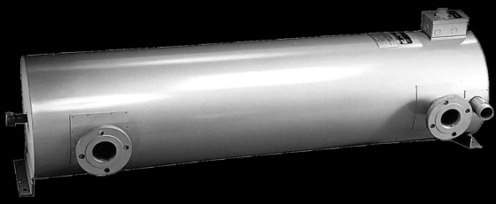
An Accutherm large circulation heater is the high-kW, large-vessel end of the circulation (inline) platform — a flange-mounted immersion-element bundle welded into a large-diameter insulated pressure vessel with inlet and outlet connections. The process fluid or gas is piped through the vessel and leaves at a controlled outlet temperature up to 1200°F, so a big flowing stream is heated by a single qualified pressure-vessel assembly without ever putting an element in the tank. Choose the large build when the load outgrows a screw-plug or small circulation unit; for corrosive marine service the Monel marine-duty circulation line and for a classified area the explosion-proof immersion line are the Accutherm answers.
Key Features & Benefits
- Built for the high-kW, large-vessel end of inline heating — the large-circulation builds are the same Accutherm circulation platform scaled up — flange-mounted immersion bundles in large-diameter vessels — so a big inline process stream is heated to setpoint by a single qualified pressure-vessel assembly. One heater for the load a screw-plug or small circulation unit cannot carry.
- Heats a flowing stream without putting an element in the tank — the process moves through the vessel and the heat is made inline, so the elements never go into the storage tank, the tank stays open for process work, and the heater pulls for service without draining the tank. Heat what is moving through the pipe, not what is sitting in a vessel.
- A welded pressure vessel, engineered to the duty — the bundle lives in a welded, insulated pressure vessel with a required outlet relief valve, marked for a specific design pressure and temperature — it drops into a pressurized loop as a qualified component. The pressure-vessel discipline the load and your inspector expect, built in.
- Handling and layout designed for a heavy assembly — large horizontal vessels ship with lifting lugs, slotted feet let the vessel grow as it heats, and the IOM calls out the pull and work space the bundle needs for service. The big-heater realities planned for, not discovered on site.
- Sheath high-temperature protection comes integral — the design carries sheath-temperature sensing at the outlet, and Accutherm recommends temperature-limiting and low-flow / low-level interlocks on every circulation heater — the protection a high-kW load demands. The safeties a large inline heater needs are part of the design, not an afterthought.
Specifications
- Operating principle
- Electric resistance (Joule) heating — AC current passes through a nickel-chromium resistance coil isolated in compacted magnesium-oxide insulation inside a tubular metal sheath. On a circulation heater that immersion-element bundle is welded into a pressure vessel; the process fluid is piped through the vessel between inlet and outlet connections and leaves at a controlled outlet temperature. The large build is the same platform scaled up to high-kW loads and large-diameter vessels.
- Mounting / installation
- Inline (circulation), flange-mounted — vessels of 3″ pipe and larger are built with pipe-flange-mounted immersion heaters (vessels of 2½″ pipe and smaller use pipe-thread / screw-plug mounting), so the large end of the line is the flanged, large-diameter configuration. The heater is built for a specific mounting orientation (vertical or horizontal) marked on the nameplate and must be installed that way; large horizontal vessels are furnished with lifting lugs to assist movement. Slotted mounting feet let the vessel thermally expand.
- Pressure vessel & nozzles
- A welded pressure vessel with inlet and outlet connections, insulated and jacketed in light-gauge sheet metal, with a low-point drain plug for draining and maintenance. On the large builds the vessel is large-diameter (3″ pipe and up) and mass is significant — the mounting location must safely support the heater weight plus the full fluid weight. Customer piping must be supported to minimize nozzle loading; expansion joints or flex hoses at the slotted end let the connections move with the heater. It is the user’s responsibility to confirm the vessel and sheath materials suit the process fluid (corrosion review).
- Relief valve & safety
- On a pressurized system a relief valve must be installed at the heater outlet. Its opening pressure shall not exceed the vessel design pressure marked on the nameplate, and it must be sized to relieve at the rate the heater can thermally expand fluid trapped by a downstream blockage. No shutoff of any type may be placed between the relief valve and the heater, or on the discharge between the valve and atmosphere. Local codes may require a combined pressure-temperature relief valve.
- Element construction
- Tubular electric-resistance immersion elements, magnesium-oxide-filled, bundled and oriented to the vessel. Multi-circuit bundles, cross-baffles, and over-temperature thermocouples are oriented to match the vessel and must not be rotated without consulting the factory. One or more factory-installed sheath high-temperature sensors are typically provided near the outlet; on a high-kW large heater this sheath-temperature protection is integral to the design. Heating elements are not field-repairable — service is by replacing the immersion heater or returning it to the factory.
- Sheath materials
- Selected to the fluid chemistry and the maximum sheath temperature it can carry — Copper 350°F, Steel 750°F, Stainless steel (304 / 316 / 321) 1400°F, and Incoloy (800 / 840) 1700°F absolute maximum sheath temperatures (other materials per UL 1030 or CSA C22.2 No. 72). The vessel material is reviewed alongside the sheath for corrosion compatibility with the process fluid.
- Process / fluid temperature
- Outlet temperatures up to 1200°F across the design range, depending on fluid, sheath, watt density, and flow. Because the large/high-kW duty drives high element surface temperatures, the design features must be closely matched to the application — outlet temperature, watt density, and flow velocity together set the element surface temperature, and element life is directly related to that surface temperature.
- Watt density
- Heating elements are available in various watt-density ratings; the rating is matched so that outlet temperature, watt density, and flow velocity hold the element surface temperature below the sheath limit and below the fluid film temperature. On a large inline heater with a brief fluid pass this is the make-or-break selection — too high a density on a low flow shortens element life or damages a heat-sensitive fluid (see the per-fluid table below).
- Fluid & sheath compatibility
- The Aspeq immersion platform matches sheath material and watt density to the process fluid — water, glycols, fuel and heat-transfer oils, caustics, acids, brine, and gases. Representative rows below show the highest-traffic process fluids; the full selection travels with the quote, and the user is responsible for confirming the wetted materials suit the actual fluid.
Recommended Sheath Material & Watt Density by Fluid
| Fluid | Fluid temp | Max W/in² | Recommended sheath |
|---|---|---|---|
| Water (clean process) | 212°F | 60–75 | Copper, Steel, 304/316 SS, Incoloy 800 |
| Water (demineralized / DI) | 180°F | 40–60 | 316 SS, Incoloy 800 |
| Glycol / water mix | 212°F | 40–60 | Copper, 304/316 SS, Incoloy 800 |
| Light fuel oil / kerosene | 200°F | 15–25 | Steel, 304 SS, Incoloy 800 |
| Heavy / Bunker oil | 180°F | 3–5 | Steel, 304 SS, Incoloy 800 |
| Heat-transfer oil (Dowtherm-A) | 500°F | 3–5 | Steel, 304/316 SS, Incoloy 800 |
| Asphalt | 300°F | 5–8 | Steel, 304 SS, Incoloy 800 |
| Caustic (NaOH 50%) | 180°F | 20–30 | Steel, 304 SS, Nickel (consult factory) |
| Acetic acid (50%) | 200°F | 20–25 | 316 SS, Monel 400, Titanium |
| Sulfuric acid (10%) | 180°F | 10–15 | 316 SS, Titanium |
| Sodium chloride brine / seawater | 180°F | 15–25 | Monel 400, Titanium, Incoloy 800 |
| Air (process, forced) | 1000°F | 15–30 | Incoloy 800, Inconel 600 |
- Wattage range
- Sized to the flow rate, the required temperature rise, and the watt density the fluid tolerates — the large-circulation builds carry the high-kW end of the circulation line, with the vessel diameter and flange size following the required kW. Field conductors must be sized for at least 125% of the circuit current; line current = kW × 1000 ÷ line voltage (single-phase) or ÷ (1.732 × line voltage) for three-phase.
- Voltage / phase
- Wound to the service voltage and phase marked on the nameplate; field supply wiring must be rated for 600 Vac and use copper conductors. The heater must not be operated above its nameplate voltage — excess voltage raises element temperature, shortens life, and can overload the branch-circuit wiring.
- Circuiting
- High-kW loads are split into multiple circuits; multi-circuit immersion bundles are oriented to the vessel and must not be rotated without consulting the factory. Each circuit is protected and controlled per the heater control panel and wiring diagram supplied with the heater.
- Thermostat options
- Temperature-regulating and temperature-limiting controls are recommended on every circulation heater to control the process and safeguard the heater from excess temperature. Sheath high-temperature sensors near the outlet are typically factory-installed; on the large/high-kW builds an over-temperature interlock that de-energizes the heater before the maximum sheath temperature is reached is integral to a safe design.
- Control integration
- Where an integral Industrial Control Panel is supplied with the circulation-heater assembly, it carries the limit, level, flow, and pressure controls the installation needs; the matched control panels provide SCR, contactor, and stepped power and control for staged high-kW loads. The end user is responsible for ensuring the provided controls operate to keep the installation safe. RTD / thermocouple sensor extension wiring between the heater and panel must be landed with correct polarity (shielded wire recommended).
- Terminal enclosure
- Review the environmental NEMA / Type / IP rating marked on the nameplate and do not install the heater in conditions inconsistent with that rating. Extended terminal boxes are typically provided where enclosure service temperatures would otherwise be exceeded, to allow element moisture seals, or to avoid costly high-temperature wire — do not insulate above the immersion-heater fitting on extended boxes unless approved by the factory.
- Hazardous-area rating
- Circulation heaters can be specially designed for hazardous areas per Article 500–516 of the National Electrical Code, Section 18 of the Canadian Electric Code, and/or UL, CSA, EN, or IEC 60079; the classification is marked on the nameplate. For a dedicated explosion-proof build (Class I, Divisions 1 & 2 and the international ATEX / IECEx marked construction) see the Accutherm explosion-proof immersion line. Never operate any heater in a combustible atmosphere unless it is specifically marked for that location.
- Approvals & listings
- Hazardous-area builds carry North-American (Class / Division / Group / T-code) and international (ATEX / IECEx) markings per the nameplate; sheath materials follow UL 1030 or CSA C22.2 No. 72. The installation must include a service disconnect in sight of the heater, branch-circuit over-current protection, and over-temperature protection, plus the user-provided low-liquid-level / low-flow interlocks the IOM requires.
- Build & lead time
- Custom build-to-order — no published price list, quote-only. Lead times typically run about 3 to 14 weeks depending on configuration, hazardous-area documentation, and code-stamp requirements.
Common Applications
- High-kW heating of a large inline process stream to a controlled outlet temperature
- Heat-transfer-fluid and thermal-oil loops on large process skids
- Fuel-oil and heavy-oil preheat at high throughput ahead of a burner or pump
- Process gas and process air heating in a large closed or once-through loop
- Large-volume water and glycol-loop heating where the elements must stay out of the tank
- Defense, marine, and heavy-industrial inline heating where the load exceeds a small circulation unit
Design & Selection Considerations
- Match watt density and flow to the fluid — it is the No. 1 failure mode — on a high-kW large heater the consequences of mis-sizing scale with the load: too high a density or too low a flow drives the element surface past the fluid film temperature, damages the fluid, and burns the sheath out (the surface-temperature relationship is in the specifications). Use the input form to give us the fluid, the flow, and the temperature rise so the density is sized, not guessed.
- Never energize against no flow or a dry vessel — do not turn the elements on until the vessel is completely full of fluid, and never run at inadequate flow rates — reduced flow shortens element life, trips thermal safeties, and can exceed the vessel shell design temperature. A low-flow / low-level interlock plus an independent high-limit are not optional. Prove flow and full immersion before the heater can fire.
- Plumb the relief valve correctly — and never valve it off — the outlet relief valve is required on a pressurized loop, set no higher than the marked vessel design pressure and sized for the heater’s thermal-expansion rate against a downstream blockage. No shutoff may sit between it and the heater, or between it and atmosphere, and its discharge must be aimed away from scald and live-part hazards. The relief path stays open at all times — do not let a valve defeat it.
- Support the weight and the nozzle loads — the mounting location has to carry the heater plus the full fluid weight, and customer piping must be supported so it does not load the inlet and outlet nozzles (the vessel spec covers how the connections accommodate thermal growth). Install slotted-foot bolts to the outside of the slots so the vessel can expand as it heats. A large vessel full of fluid is heavy — design the structure and the piping for it.
- Leave real pull and work space at layout — the immersion bundle withdraws from the vessel for inspection or replacement — the IOM calls for pull space at least the nozzle-to-nozzle length plus two feet, and at least three feet of work space in front and on either side. Easy to omit on the P&ID for a big heater, expensive to discover at the first service call.
- Do not rotate a multi-circuit bundle in the field — on a high-kW heater the bundle is oriented to the vessel for a reason (the spec covers what the orientation serves); rotating the immersion heater during reinstallation without the factory’s guidance can defeat the baffling and the sensor placement. Mark the orientation before removal and put it back the same way.
- Megger and bake out after storage — the magnesium-oxide insulation absorbs atmospheric moisture over long storage; a heater off the shelf can read low insulation resistance. If a 500 Vdc megger reads below 1 meg-ohm, dry the elements out at reduced voltage with the terminal lid open before service. A “bad” new heater is usually just damp MgO.
To size the right Accutherm large circulation heater:
Use the input form to send your fluid or gas, target temperature rise (ΔT) and maximum outlet temperature, flow rate range (min / max), maximum design pressure and pressure drop, the heater environment (hazardous / corrosive / weatherproof), voltage and phase available, and the temperature-control method — and we’ll spec the right Aspeq heater & control package for your application.
Electric Heating Application Sheet ›Talk to an engineer directly — Scott Prater, Principal · 917-580-0878 · scott@pratertechnical.com
Specifications compiled by Prater Technical Partners from Aspeq Heating Group product datasheets.