Product Overview
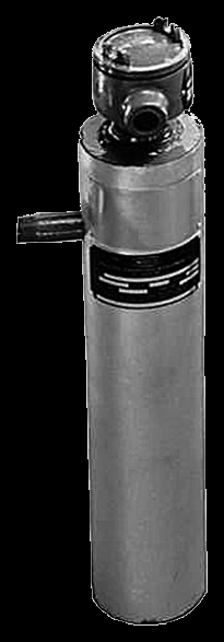
An Accutherm vertical circulation heater is the standard circulation platform — a tubular immersion-element bundle built into a welded pressure vessel the process fluid is piped through — built and stamped for vertical, floor-mounted installation. The vertical orientation is the point: the vessel stands on mounting feet in a tight footprint, gravity vents trapped air at the high point and drains at the low-point plug, and the heater leaves the fluid at a controlled outlet temperature without ever going into the tank. It is built for one orientation and must be installed that way; for a horizontal inline run or for heating a volume held in a tank, the standard circulation and the flanged / screw-plug immersion builds are the answer.
Key Features & Benefits
- Built and stamped for vertical mounting — the vessel is engineered for one orientation and floor-mounted on feet that carry the vessel and its fluid weight, so it drops straight into a stacked skid or a tight footprint where a horizontal heater would not fit. The right shape when the floor space is the constraint, not the ceiling.
- Vents and drains by gravity — with the vessel vertical, the high point vents trapped air and the low-point drain plug empties it — the two things that, left undone, cause the air pockets and dead legs that overheat an inline heater. Orientation doing the venting and draining work for you.
- Heats a flowing stream, not a tank — the element bundle lives inside the pressure vessel the fluid is piped through, so the process leaves at setpoint without a heater ever going into the tank. The element stays clear of tank sludge and pulls for service without draining the tank.
- Watched for the two fault modes that kill inline heaters — the factory temperature sensing and the recommended low-level and low-flow controls de-energize the heater before it ever runs dry or starves for flow. Dry-fire and no-flow, both designed against from the start.
- Matched to the fluid at the design stage — sheath material and watt density are chosen against the fluid chemistry and outlet temperature, because the fluid only passes the element briefly. The specification is built to the process, not pulled from a shelf.
Specifications
- Operating principle
- Electric resistance (Joule) heating — a tubular immersion-element bundle, with nickel-chromium resistance wire in compacted magnesium-oxide insulation inside a metal sheath, is built into a welded pressure vessel with inlet and outlet connections. The process fluid is piped through the vessel in a loop and leaves at a controlled outlet temperature — here the vessel is built for vertical mounting.
- Mounting / installation
- Vertical (top-down / floor-mounted) circulation — the vessel is built for one specific orientation and, per the IOM, "must be mounted in this manner, to prevent improper operation or damage." The standard vertical arrangement (the IOM’s Vertical Floor Mounting figure) carries the vessel on mounting feet / channels that the installer bolts to the floor; the channels are drilled by the user and slotted holes are run to the outside so the vessel can thermally expand. The correct figure number is called out on the heater nameplate / Application Data with the order.
- Pressure vessel & nozzles
- A welded pressure vessel with the inlet and outlet nozzles plumbed to the vessel and a low-point drain plug for draining and sludge removal. Vessels of 3″ pipe and larger typically use a pipe-flange-mounted immersion heater; vessels of 2½″ pipe and smaller use a pipe-thread (screw-plug) mounted heater. The vertical vessel must be set plumb — level both ways — so the fluid flows and the heater vents and drains correctly. Insulation with a light-gauge metal jacket is typically furnished on the shell.
- Relief valve & safety
- On a pressurized system an outlet relief valve is required, set no higher than the vessel design pressure and sized to relieve the rate at which the heater can thermally expand fluid trapped by a downstream blockage. It mounts as close as possible to the outlet and must stay accessible; no shutoff of any kind may sit between the relief valve and the heater, or between the valve and atmosphere. A pressure-temperature relief valve is used where local code requires it.
- Element construction
- Tubular immersion elements with nickel-chromium resistance wire in compacted magnesium-oxide insulation. One or more factory-installed sheath high-temperature sensors are typically fitted near the outlet to de-energize the heater before the maximum sheath temperature is reached. The elements are not field-repairable — service is by removing and replacing the immersion heater or returning it to the factory.
- Sheath materials
- Copper · steel · stainless steel (304 / 316 / 321) · Incoloy (800 / 840) — chosen for the process fluid’s chemistry and maximum temperature (absolute sheath-temperature limits are in the table below). The user is responsible for confirming the construction materials suit the process fluid — corrosion in particular.
Sheath Material — Absolute Maximum Sheath Temperature
| Sheath material | Maximum sheath temperature |
|---|---|
| Copper | 350°F (177°C) |
| Steel | 750°F (399°C) |
| Stainless steel (304/316/321) | 1400°F (760°C) |
| Incoloy (800/840) | 1700°F (927°C) |
- Process / fluid temperature
- Outlet temperatures up to 1200°F across the design range, depending on fluid, sheath, and watt density. Outlet temperature, watt density, and flow velocity together set the element surface temperature, and element life is directly tied to that surface temperature — so the design features must be closely matched to the application at these temperatures.
- Watt density
- The heating elements are offered in a range of watt-density ratings; the rating is matched to the fluid and to the outlet temperature, because watt density, outlet temperature, and flow velocity together set the element surface temperature that governs element life. On a liquid system, too high a density (or too low a flow) drives the fluid film temperature past what the fluid tolerates and damages it.
- Control integration
- Aspeq recommends temperature-regulating, temperature-limiting, low-liquid-level, and low-flow controls on every circulation heater — a factory sheath high-temperature sensor near the outlet ties into them to de-energize the heater before the sheath overheats or before the elements are uncovered. Where a control panel is supplied integral to the assembly, the end user is responsible for verifying that the limit, level, flow, and pressure controls operate as needed to keep the installation safe.
- Terminal enclosure
- Review the NEMA / Type / IP environmental rating marked on the heater nameplate or Application Data and install only in an area consistent with it. An extended terminal box is typically provided where enclosure service temperature would otherwise be exceeded, to allow element moisture seals, or to avoid high-temperature field wire — do not insulate above the immersion-heater fitting on an extended box unless the factory approves it.
- Hazardous-area rating
- Circulation heaters can be specially designed for hazardous areas per NEC Articles 500–516, Canadian Electrical Code Section 18, and UL / CSA / EN / IEC 60079. For a dedicated classified-area build (Class I, Divisions 1 & 2) see the Accutherm explosion-proof immersion line; on a vertical circulation vessel the area classification, Group, and temperature code are confirmed against the nameplate per the order. Consult the factory with the classification.
- Approvals & listings
- Built as a welded pressure vessel; an outlet relief valve, over-temperature protection, and a low-liquid-level / low-flow interlock are required on the installation per the IOM and local code. The user is responsible for verifying the construction materials suit the process fluid and for confirming the area classification.
- Build & lead time
- Custom build-to-order — no published price list, quote-only. Lead times typically run about 3 to 14 weeks depending on configuration, hazardous-area documentation, and code-stamp requirements.
Common Applications
- Inline heating where floor space, not headroom, is the constraint — stacked or tight-footprint skids
- Heat-transfer-fluid and glycol loops brought up to setpoint on a process skid
- Fuel-oil and heavy-oil preheat to cut viscosity ahead of a burner or pump — power, oil & gas
- Lubrication- and hydraulic-oil heating for cold-weather start-up
- Indirect tank, sump, and reservoir heating where the elements must stay out of the vessel
- Booster heating just ahead of the point of use
Design & Selection Considerations
- Set it plumb, and pipe it so it vents — install the vessel dead level in both planes and route the piping so the high point bleeds trapped air and the low point drains. Trapped air pockets cause improper operation and can damage the heater — the IOM calls this out directly.
- Honor the flow direction marked on the nozzles — the inlet and outlet markings are real — the heater may carry instruments that will not work if flow is reversed, and the field markings can even be opposite the reference figure. Pipe to the "Inlet" and "Outlet" on the heater, not to a generic drawing.
- No flow is as dangerous as no fluid — never energize the elements until the vessel is completely full, and interlock the heater to proven flow. A low-level control, a flow control, and an independent high-limit are recommended, not optional — dry or low-flow operation overheats the sheath fast. Fill, prove flow, then energize.
- Plumb the relief valve correctly — and never valve it off — on a pressurized loop, run no shutoff between the relief device and the heater or between it and atmosphere, and aim the discharge away from people and live parts. The relief path has to stay open at all times — design it in, do not let a valve defeat it.
- Leave pull clearance to service the bundle — the immersion heater withdraws from the vessel for inspection or replacement — the IOM calls for pull space of at least the inlet-to-outlet nozzle length plus two feet, and about three feet of working space in front and to the sides. On a vertical heater that pull space is overhead — check the headroom at layout.
- Allow for thermal growth at the supports and piping — the vessel grows with temperature (the IOM gives an expansion estimate from the nozzle-to-nozzle length); bolt the feet through slotted holes to the outside, skip lock washers, and use expansion joints or flex hoses so nozzle loading does not crack the vessel. Let it move, or it will leak.
- Match the sheath to the fluid temperature, and confirm it suits the chemistry — each sheath has an absolute maximum temperature (copper 350°F, steel 750°F, stainless 1400°F, Incoloy 1700°F — see the table); staying under it is necessary but not sufficient, because the alloy also has to resist the process chemistry. Temperature limit and corrosion are two separate checks — the fluid has to clear both.
- Megger and bake out after storage — the magnesium-oxide insulation absorbs atmospheric moisture in storage, so a shelved heater can read low insulation resistance. If it reads under 1 MΩ on a 500 Vdc tester, dry it out at reduced voltage with the terminal lid open before service. A "bad" new heater is usually just damp MgO.
To spec the right Accutherm vertical circulation heater:
Use the input form to send your fluid or gas, target temperature rise (ΔT) and maximum outlet temperature, flow-rate range (min / max), maximum design pressure, the available headroom and floor footprint for a vertical vessel, the heater environment (hazardous / corrosive / weatherproof), and the voltage and phase available — and we’ll spec the right Accutherm vertical circulation heater and control package for your installation.
Electric Heating Application Sheet ›Talk to an engineer directly — Scott Prater, Principal · 917-580-0878 · scott@pratertechnical.com
Specifications compiled by Prater Technical Partners from Aspeq Heating Group product datasheets.