Product Overview
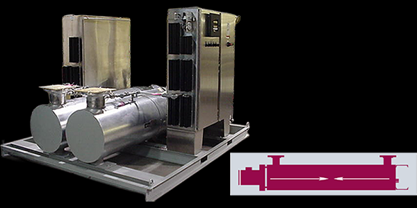
A circulation (inline) heater is an immersion element built into a thermally insulated pressure vessel with inlet and outlet nozzles — the process fluid or gas is piped through it and leaves at a controlled outlet temperature, so nothing goes into the tank. That makes it the answer for heating a flowing stream: heat-transfer-fluid loops, fuel- and lube-oil preheat, process gas, and indirect tank heating where the elements must stay out of the vessel. Choose circulation when the fluid moves through a pipe; for heating a volume held in a tank, the flanged, screw-plug, and over-the-side immersion builds are the answer.
Key Features & Benefits
- Heats a flowing stream to a controlled outlet temperature — the element sits in an insulated pressure vessel the fluid is piped through, so the process leaves at setpoint without ever putting a heater in the tank. The answer when you need to heat what is moving through a pipe, not what is sitting in a vessel.
- Keeps the element out of the tank — because the heat is made inline, the elements stay clear of sludge build-up and physical damage, the tank interior stays open for process work, and the heater pulls for service without draining the tank. The tank stays clean and serviceable; the heater does too.
- Built and stamped as a pressure vessel — the vessel is engineered to ASME standards with an optional Section VIII “U” Code stamp and a required outlet relief valve, so it drops into a pressurized loop as a qualified component. The paperwork your inspector and insurer expect on a pressure vessel, built in.
- Engineered against the hot spot that kills inline heaters — the construction keeps the elements evenly spaced and free to expand, so no element bakes a neighbor or scorches a passing temperature-sensitive fluid (the spacer detail is in the specifications). The No. 1 inline-heater failure mode, designed out.
- Factory thermostat, or a matched control panel — a pre-wired bulb-and-capillary thermostat handles a standalone heater; larger or tighter-control jobs take a matched contactor, SCR, or stepped panel with overtemperature and flow-interlock protection. Plug-and-go on a small loop; full process control when the load or the tolerance grows.
Specifications
- Operating principle
- Electric resistance (Joule) heating — AC current passes through a nickel-chrome coil in compacted magnesium-oxide insulation inside a metal sheath. On a circulation heater the element bundle is built into an insulated pressure vessel; the process fluid or gas is piped through the vessel in a closed loop (or once-through) and leaves at a controlled outlet temperature.
- Mounting / installation
- Inline (circulation) — the heater is plumbed into the process line through inlet and outlet nozzles, so it heats a flowing stream rather than a tank. Six factory mounting options (vertical and horizontal among them) suit the installation; the mounting configuration is specified with the order.
- Pressure vessel & nozzles
- Immersion element in a thermally insulated pressure vessel with inlet and outlet nozzles and a drain plug for periodic sludge removal. Standard vessel material is carbon steel; a stainless-steel vessel (and other alloys — Incoloy, copper-nickel) is available for higher temperatures or better corrosion resistance. The heater is a pipe-thread or pipe-flange immersion bundle; nominal configurations run from a 2½″ pipe-thread vessel up through 3″, 5″, 8″, 10″, and larger flange sizes, with custom vessel diameters available to suit the kW. Inlet and outlet connections are NPT or flanged, specified with the order.
- Relief valve & safety
- On any pressurized system an outlet relief valve is required — supplied built-on or as a loose accessory. No shutoff of any kind may be placed between the relief valve and the heater, or on the discharge between the valve and atmosphere. A customer-supplied expansion chamber is recommended where the piping includes a fast-acting or check valve.
- Element construction
- Compacted tubular elements, magnesium-oxide filled, assembled in a low-pressure-drop bundle. Element spacers — of material similar to the element sheath — hold a uniform distance between elements to prevent the hot spots that shorten element life or scorch a temperature-sensitive fluid, and are installed so each element can expand and contract freely. Moisture-resistant epoxy terminal seals are standard, and a built-in Type J or K thermocouple is available to monitor process or sheath temperature.
- Sheath materials
- Steel · copper · 304 / 316 / 321 stainless steel · Incoloy 800 / 840 — matched to the fluid’s chemistry and maximum temperature (see the sheath / watt-density table below); other sheath alloys available. The vessel material is selected alongside the sheath: carbon steel standard, stainless steel for higher temperature or corrosion resistance.
- Cold (unheated) section length
- Unheated (cold) section at the element ends keeps the heat away from the terminal enclosure where the element exits the vessel. An extended terminal enclosure is furnished for higher-temperature service — required when the outlet temperature exceeds 400°F for gases or 450°F for liquids — so the elements keep their epoxy seals and the incoming field wire can use 90°C-rated insulation instead of a costlier high-temperature wire.
- Terminal seals
- Moisture-resistant epoxy or RTV terminal seals are standard to keep moisture out of the heating elements. Higher-temperature service uses the extended terminal enclosure (above); for an absolute moisture seal, hermetically sealed (ceramic-to-metal) element terminations are available.
- Process / fluid temperature
- Maintains, raises, preheats, or boosts process temperature from −50°F to 1200°F across the catalog range, depending on fluid, sheath, and vessel construction. The vessel’s standard 1″ thermal-insulation wrap can be replaced with thicker and/or higher-temperature insulation to extend the envelope and minimize heat loss.
- Process / vessel pressure
- The vessel is built to ASME standards; the standard design is rated 160 psi at 250°F with a Class 150 flange. An optional ASME Section VIII Div. 1 “U”-part Code stamp is available (with PED 2014/68/EU or UK PE(S)R compliance for export), and custom designs are built for pressures above the standard 160 psi rating. Specify the maximum design pressure with the quote.
- Watt density
- Watt density (W/in² of element surface) is matched to the process fluid (see table below) and to the maximum outlet temperature — the single most important selection factor on an inline heater, because the fluid passes the element only briefly. Set it too high and a fuel or heat-transfer oil carbonizes or breaks down chemically. The Aspeq immersion selection table (Table I) is the source of record; the kW is sized to the flow, the temperature rise, and the safe watt density at quote time.
- Fluid & sheath compatibility
- The Aspeq immersion platform publishes a per-fluid sheath-and-watt-density selection table covering 90+ process fluids — water, glycols, fuel and heat-transfer oils, asphalt, caustics, acids, and gases (air, nitrogen, steam). Representative rows below show the highest-traffic process fluids; the full table travels with the quote.
Recommended Sheath Material & Watt Density by Fluid
| Fluid | Fluid temp | Max W/in² | Recommended sheath |
|---|---|---|---|
| Water (clean process) | 212°F | 60–75 | Copper, Steel, 304/316 SS, Incoloy 800 |
| Water (demineralized / DI) | 180°F | 40–60 | 316 SS, Incoloy 800 |
| Glycol / water mix | 212°F | 40–60 | Copper, 304/316 SS, Incoloy 800 |
| Light fuel oil / kerosene | 200°F | 15–25 | Steel, 304 SS, Incoloy 800 |
| Heavy / Bunker oil | 180°F | 3–5 | Steel, 304 SS, Incoloy 800 |
| Heat-transfer oil (Dowtherm-A) | 500°F | 3–5 | Steel, 304/316 SS, Incoloy 800 |
| Asphalt | 300°F | 5–8 | Steel, 304 SS, Incoloy 800 |
| Caustic (NaOH 50%) | 180°F | 20–30 | Steel, 304 SS, Nickel (consult factory) |
| Acetic acid (50%) | 200°F | 20–25 | 316 SS, Monel 400, Titanium |
| Sulfuric acid (10%) | 180°F | 10–15 | 316 SS, Titanium |
| Sodium chloride brine / seawater | 180°F | 15–25 | Monel 400, Titanium, Incoloy 800 |
| Air (process, forced) | 1000°F | 15–30 | Incoloy 800, Inconel 600 |
- Wattage range
- Sized to the flow, the temperature rise, and the watt density the fluid tolerates — per the catalog KW sizing equation and listing tables, matched at quote time. The vessel and flange size follow the required kW and watt density.
- Voltage / phase
- 120 V, 208 V, 240 V, 277 V, and 480 V standard, single- and three-phase — and any voltage up to 600 V (380 / 400 / 415 / 440 V among them) wound to order for a custom design.
- Circuiting
- A single-stage heater runs one circuit; larger loads and tighter outlet control are split into multiple circuits for two-stage, stepped, or SCR-trim schemes paired with a matching control panel. Three-phase circuits are balanced using a multiple of three elements per circuit.
- Bus bars
- Permanent bus bars with pressure connectors for field wiring prevent the loose connections that cause field failures. Copper bus bars are standard; stainless-steel bus bars are used on high-temperature heaters.
- Thermostat options
- Bulb-and-capillary thermostats — pilot-duty or load-carrying — can be provided to control the heater or for over-temperature protection, with the bulb installed in a thermowell to sense process or element-sheath temperature. Built-on thermostats and contactors are an optional factory package; larger heaters use a pilot-duty thermostat switching a magnetic contactor.
- Control integration
- Matched factory control packages: contactor panels for on/off duty, SCR power controllers for proportional and tight-tolerance outlet control, and stepped / sequenced schemes for staged loads. A built-on over-temperature thermostat, a built-in thermocouple or RTD, and a pump / flow-switch interlock are available; Aspeq recommends process over-temperature protection on every circulation system.
- Terminal enclosure
- Standard construction is not rated for wet or hazardous locations. Weatherproof / corrosion-resistant (NEMA 4) and explosion-resistant (NEMA 7) terminal enclosures are available where required, with a high-temperature insulation jacket or a partially-welded protective steel shroud (steel, 304 / 316 stainless, or aluminum) to guard against weather and wash-down.
- Hazardous-area rating
- Hazardous-location construction (pipe-flange heaters) is available, classified by the National Electrical Code as Class I, Division 1, Groups B, C & D and Class I, Division 2, Groups A, B, C & D, plus Class II, Division 1, Groups E, F & G; ATEX / IECEx (Ex db IIB+H2 Gb / Ex tb IIIC Db, IP66) and CSA marking are available for export. Consult the factory with the area classification, Group, and required T-code.
- Approvals & listings
- ASME Section VIII Div. 1 “U”-part Code stamp available (PED 2014/68/EU and UK PE(S)R compliance for export); CSA approval for ordinary and hazardous locations along with ATEX and IECEx certification. The user is responsible for the outlet relief valve, process overtemperature protection, and a low-liquid / no-flow interlock per the IOM and local code.
- Build & lead time
- Custom build-to-order — no published price list, quote-only. Lead times typically run about 3 to 14 weeks depending on configuration, hazardous-area documentation, and code-stamp requirements.
Common Applications
- Bringing a heat-transfer-fluid loop (Dowtherm, Therminol, glycol) up to setpoint — process skids
- Fuel-oil and heavy-oil preheat to cut viscosity ahead of a burner or pump — oil & gas, power
- Process air, nitrogen, and gas heating in a closed or once-through loop
- Lubrication- and hydraulic-oil heating for cold-weather start-up — engines, gensets, test stands
- Booster heating just ahead of the point of use — steam cleaning, washdown, high-temp process gas
- Freeze protection and indirect tank heating where the elements must stay out of the tank
Design & Selection Considerations
- Watt density is the make-or-break spec — set it by the fluid — an inline heater gives the fluid only a brief pass over the element, so too high a W/in² carbonizes oils, breaks heat-transfer fluids down, and burns the sheath out. Use the input form to tell us the fluid and we work backward to a safe density (see the per-fluid range in the specifications). This is the No. 1 reason circulation heaters fail early.
- No flow is as dangerous as no fluid — a circulation heater energized against a closed valve or a dead pump overheats fast. A flow switch or pump interlock, plus an independent high-limit, are not optional. Interlock the heater to proven flow and you eliminate the most common field failure.
- Plumb the relief valve correctly — and never valve it off — the outlet relief valve is a code requirement on a pressurized loop; no shutoff may sit between it and the heater, or between it and atmosphere. Add an expansion chamber where a fast-acting or check valve can trap pressure. The relief path has to stay open at all times — design it in, do not let a valve defeat it.
- Mind the pressure drop, especially on viscous oil — the vessel adds head loss that climbs steeply with viscosity — SAE 30 oil runs roughly 1.6× the water pressure drop, and viscosity swings sharply with inlet temperature. Size the pump and the vessel together. Use the input form to give us the fluid and the cold-start inlet temperature so the pressure drop is real, not nominal.
- Leave pull space to service the element — the immersion bundle withdraws from the vessel for inspection or replacement — leave roughly its length of clearance in front of the heater at the layout stage. Easy to forget on the P&ID, expensive to discover at the first service call.
- Match the vessel and sheath to the fluid, not just the sheath — on an inline heater the carbon-steel vessel sees the fluid as much as the sheath does; corrosive or high-purity service wants a stainless (or higher-alloy) vessel as well as the right sheath. Spec the wetted vessel to the chemistry, not only the element.
- Set the control to the tolerance you actually need — the built-in thermostat suits a forgiving loop; a tight outlet ΔT or a heat-sensitive fluid wants SCR or stepped control for fine resolution and soft-start. Pick the required turndown before you pick the panel.
- Megger and bake out after storage — the magnesium-oxide insulation is hygroscopic, so a heater off the shelf can read low insulation resistance. Megger it and bake out the absorbed moisture before putting it in service. A “bad” new heater is usually just damp MgO.
To spec the right Indeeco circulation heater:
Use the input form to send your fluid or gas, target temperature rise (ΔT) and maximum outlet temperature, flow rate range (min / max), maximum design pressure and pressure drop, the heater environment (hazardous / corrosive / weatherproof), voltage and phase available, and the temperature-control method — and we’ll spec the right Aspeq heater & control package for your application.
Electric Heating Application Sheet ›Talk to an engineer directly — Scott Prater, Principal · 917-580-0878 · scott@pratertechnical.com
Specifications compiled by Prater Technical Partners from Aspeq Heating Group product datasheets.