Product Overview
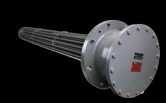
The flanged immersion heater is Aspeq Heating Group’s workhorse build for the demanding end of immersion heating — larger kW, higher pressures, ASME-code vessels, and hazardous-area service. The element bundle is attached to a circular ANSI flange that bolts to a matching flange on the tank or vessel, so a single heater can move hundreds of kW into a pressurized vessel and still unbolt as a unit for service. Choose the flanged style when pressure, total kW, or area classification rule out a screw-plug heater; for smaller tanks and lower-pressure duty, the screw-plug and over-the-side builds are the lighter-weight answer. Sheath alloy, watt density, voltage, controls, and code stamping are all configured to the application — the specifications and the design considerations below walk through those choices.
Key Features & Benefits
- ASME Section VIII Code-stamp available — a Class 150 flange covers everyday line pressures; stepping up to Class 300 and a Section VIII Code stamp takes the heater into pressurized-vessel territory (the exact ANSI ratings are in the specifications). If the heater bolts into a pressure vessel, the Code stamp is the paperwork your inspector and insurer look for.
- Three terminal-seal options, matched to the heat — moisture-resistant epoxy to 250°F, mica insulators for higher-temperature service with no epoxy, and ceramic-to-metal hermetic seals to 1000°F. The seal keeps moisture out of the terminal box — the right one for your temperature is what prevents nuisance ground-faults.
- Welded stainless bus bars — bus bars are permanently welded rather than bolted, so they cannot loosen and arc in high-temperature service. No bolted bus connection to back out and burn up — one less thing that fails in the field.
- Explosion-proof for Class I & II hazardous locations — the flanged build is listed for hazardous locations — UL Type 4 / 4X with ATEX / IECEx for export — the Groups and Temperature-Code detail are in the specifications. Mandatory where the area is classified — give us the Group and T-code and the heater is built to match.
- Matched factory control packages — contactor, SCR, S5 / S10 step controller, or Vernier hybrid — with a PID temperature loop and an independent high-limit safety — engineered and supplied with the heater. The heater and its panel arrive built for each other, so commissioning is wire-and-go instead of integrate-and-hope.
Specifications
- Operating principle
- Electric resistance (Joule) heating — AC current passes through a high-resistance nickel-chrome coil embedded in compacted magnesium-oxide insulation inside a metal sheath. On a flanged immersion heater the element bundle is attached to a circular flange that bolts to a matching flange on the tank or vessel; the sheath sits directly in the process fluid or gas with essentially 100% efficiency. No flame, no flue.
- Mounting / installation
- Flanged immersion — the element bundle is attached to a circular flange that bolts to a matching flange on the tank or vessel. The flanged style is the choice for larger heaters, higher pressures, ASME-code service, and hazardous-area construction, where flange ratings, gasket selection, and terminal enclosure type all matter. Bottom-mounted, rectangular flange, and Series 770 flange variants available for specialty applications.
- Flange sizes & ratings
- ANSI Class 150 and Class 300 raised-face flanges, nominal 3″ through 18″ common, with standard ANSI sizes through 26″ available on engineered builds. Bolt patterns per the published Class 150 / Class 300 flange dimension tables (ANSI B16.5). Lifting rings provided on all flanges 4″ and larger to facilitate handling.
- Element construction
- .475″ O.D. compacted tubular elements, magnesium-oxide (MgO) filled and high-pressure-roller compacted, with all U-bends repressed for dielectric integrity. The large element diameter provides extra electrical insulation, making the standard element suitable for line voltages up to 600 V. Copper-sheathed elements are silver-soldered to the flange; higher-alloy sheaths are welded. Sheath thermocouples, by contrast, are clamped to the sheath rather than welded through it — an Aspeq reliability philosophy, since a weld penetration risks a pinhole that becomes a moisture-ingress and shorting failure point over the life of the heater.
- Sheath materials
- Steel · copper · 304 stainless steel (the Aspeq standard) · 316 / 321 stainless steel · Incoloy 800 / 840 · Inconel 600 · Monel 400 · titanium, with other sheath alloys available on request. Selection is matched to the fluid’s chemistry and temperature (see the sheath / watt-density table below); Incoloy can always replace steel or stainless steel.
- Header / fitting materials
- Header / flange standard in steel or 304 stainless steel; Incoloy 800, Inconel 600, 316 stainless steel, and Monel 400 available as special-order options. The header material is selected for chemical compatibility at the wetted side of the flange.
- Cold (unheated) section length
- Unheated (cold) section at the element ends prevents sheath overheating where the element exits the liquid. Standard cold ends: 2″ minimum for copper, steel, and stainless-steel sheaths; 5″ minimum for Incoloy. Vertically-mounted heaters and applications where the fluid may not fully cover the elements need a longer cold end — specify on order. Extended terminal enclosures are available for additional heat separation between the process and the electricals.
- Terminal seals
- Three seal options matched to operating temperature: moisture-resistant epoxy seals standard on copper-sheathed heaters to 250°F fluid temperature; mica terminal insulators standard on steel, stainless, and Incoloy sheaths (no epoxy) for higher-temperature service; ceramic-to-metal hermetic seals available for applications requiring an absolute moisture seal to 1000°F.
- Process / fluid temperature
- Copper-sheath builds are limited to 250°F by the standard epoxy terminal seal. Steel, stainless, Incoloy, and Inconel sheaths with mica or hermetic seals extend the envelope much higher — the explosion-proof flanged line is rated to 1200°F (650°C) process temperature, with the sheath alloy (Incoloy 800 / Inconel 600 at the top end) selected to the fluid and the duty. Specify the maximum process temperature with the order; sheath selection, cold-end length, and terminal seal are matched to it.
- Process / vessel pressure
- Pressure rating follows the flange’s ANSI B16.5 class: a Class 150 steel flange is rated about 285 psi at ambient and ~260 psi at 200°F, declining with fluid temperature per B16.5 (Type 304 stainless Class 150 ~275 / 235 / 205 psi over the same range). Class 300 flanges and ASME Section VIII Code-stamped vessels take the pressure higher. Specify the maximum design pressure with the quote.
- Watt density
- Watt density (W/in² of element surface) is matched to the process fluid (see table below) and to the maximum process temperature. Indeeco Table I is the source of record. General reference across the range: clean circulating water ~60–75 W/in² at the high end (water is an excellent convector), oils and heat-transfer fluids ~20 W/in² mid-range, and heavy / viscous or heat-sensitive fluids well under 10 W/in² at the low end — the lower the density, the cooler the sheath film, which is what keeps a sensitive fluid from coking or scaling. Catalog standard heaters are designed for a maximum outlet-box temperature of 250°F with one electrical circuit per single-stage operation unless multiple circuits are specified.
- Fluid & sheath compatibility
- The Aspeq immersion platform publishes a per-fluid sheath-and-watt-density selection table covering 90+ process fluids — water, glycols, fuel and heat-transfer oils, asphalt, caustics, acids, brines and seawater, refrigerants, and forced air. Representative rows below show the highest-traffic process fluids; the full table travels with the quote.
Recommended Sheath Material & Watt Density by Fluid
| Fluid | Fluid temp | Max W/in² | Recommended sheath |
|---|---|---|---|
| Water (clean process) | 212°F | 60–75 | Copper, Steel, 304/316 SS, Incoloy 800 |
| Water (demineralized / DI) | 180°F | 40–60 | 316 SS, Incoloy 800 |
| Glycol / water mix | 212°F | 40–60 | Copper, 304/316 SS, Incoloy 800 |
| Light fuel oil / kerosene | 200°F | 15–25 | Steel, 304 SS, Incoloy 800 |
| Heavy / Bunker oil | 180°F | 3–5 | Steel, 304 SS, Incoloy 800 |
| Heat-transfer oil (Dowtherm-A) | 500°F | 3–5 | Steel, 304/316 SS, Incoloy 800 |
| Asphalt | 300°F | 5–8 | Steel, 304 SS, Incoloy 800 |
| Caustic (NaOH 50%) | 180°F | 20–30 | Steel, 304 SS, Nickel (consult factory) |
| Acetic acid (50%) | 200°F | 20–25 | 316 SS, Monel 400, Titanium |
| Sulfuric acid (10%) | 180°F | 10–15 | 316 SS, Titanium |
| Sodium chloride brine / seawater | 180°F | 15–25 | Monel 400, Titanium, Incoloy 800 |
| Air (process, forced) | 1000°F | 15–30 | Incoloy 800, Inconel 600 |
- Wattage range
- Catalog standard wattages run from ~1.5 kW on small single-element 120 V builds up through multi-element 480 V flange units; the engineered flanged platform reaches 8.5 MW per heater on the largest multi-bundle assemblies. Per-element wattage and total bundle kW are matched to the required watt density and element-surface area at quote time.
- Voltage / phase
- 120 V, 208 V, 240 V, 277 V, and 480 V standard, single- and three-phase — and wound to order for the full range of NEC and international service voltages up to the 600 V dielectric rating of the .475″ standard element. Three-phase circuits are always balanced using a multiple of three elements per circuit.
- Circuiting
- Catalog standard: one electrical circuit, single-stage operation, with outlet box temperature designed for 250°F maximum. On the engineered flanged build, heater circuits are divided at 48 A maximum per circuit by default (larger circuits available on request). Multiple circuits enable two-stage and SCR-trim control schemes paired with matching panels.
- Bus bars
- Stainless steel bus bars permanently welded in place — eliminates field failures from loose bus connections that can occur in high-temperature service. Copper bus bars are used on lower-temperature heaters where amperage is high and the joint stays cool.
- Thermostat options
- Built-in single-pole, single-throw (SPST) thermostats standard on all single-phase heaters and pilot-duty applications. Double-pole, single-throw (DPST) available where a pilot light or on/off switch is required. Standard temperature ranges: 0–100°F, 40–120°F, and 60–250°F (specify range on order). Thermostat mounted inside the terminal box.
- Control integration
- Matched factory control packages cover the full spectrum: contactor panels for on / off duty cycle, SCR power controllers for proportional and tight-tolerance outlet-temperature control, S5 / S10 step controllers for multi-stage sequencing, and Vernier Controls (hybrid step + SCR-trim) for SCR-grade precision at step-controller cost. PID temperature loop with thermocouple or RTD input plus an independent high-limit safety are standard on factory panels.
- Terminal enclosure
- Standard outlet box: NEMA 1 general-purpose. NEMA 4 liquidproof — cast box with threaded, gasketed cover and 1″ NPT female-threaded hubs for electrical connections — available where moisture entering the outlet box is a concern. Welded steel NEMA 4 with enamel finish, gasketed cover, and visible-pilot-light option also offered. Stainless-steel outlet box option available. “Omit outlet box” available where field-furnished enclosures protect the terminals.
- Hazardous-area rating
- Explosion-proof flanged construction available for hazardous locations — approved area classifications Class I, Division 1, Groups B, C, and D and Class I, Division 2, Groups A, B, C, and D (flammable gases and vapors) plus Class II, Division 1, Groups E, F, and G (combustible dusts), with a UL Std 50 Type 4 / 4X enclosure and ATEX / IECEx certification for export. The Temperature-Code rating falls anywhere in the full T1–T6 range depending on the maximum process temperature relative to the code; specify the area classification, Group, and required T-code with the quote.
- Ambient temperature
- Standard catalog: 40°C / 104°F maximum ambient. The explosion-proof flanged build is rated for a wider −60°C to 60°C ambient; higher-ambient and outdoor / weatherproof variants on request.
- Approvals & listings
- UL / CSA listings available on standard catalog heaters; the explosion-proof flanged line carries a UL Std 50 Type 4 / 4X enclosure with ATEX and IECEx certification. ASME Section VIII Code-stamp available on flanged vessels. NEC compliance with Articles 500–516 (and CEC Part 1 Section 18) governs hazardous-location installation; user is responsible for installing required high-temperature limit and, on tank applications, low-liquid-level control.
- Build & lead time
- Custom build-to-order — no published price list, quote-only. Lead times typically run about 3 to 14 weeks depending on configuration, hazardous-area documentation, and code-stamp requirements.
Common Applications
- Keeping crude, fuel, and heavy oils at pumpable viscosity — oil & gas pipeline, terminal, and refinery flanged vessels
- Holding reactor feed, jacketed vessels, and tank-farm storage at process temperature — petrochemical & chemical processing
- Sanitary hot water and tank heating for CIP / SIP cycles — food & beverage
- Freeze protection and process heating for chemical-feed tanks and digesters — water & wastewater
- Heating clean water and process tanks to validated temperatures — pharmaceutical
- Bringing a heat-transfer-fluid loop up to setpoint — flanged vessel in the circulation skid
- Process heating inside a classified area — Class I & II with explosion-proof (UL / ATEX / IECEx) construction
- High-pressure / high-temperature fluid service — ASME Code-stamped flanged vessels
Design & Selection Considerations
- Watt density is the make-or-break spec — set it by the fluid, not the footprint — too much W/in² drives the sheath film temperature past what the fluid tolerates: oils coke, hard water scales, glycols and heat-transfer fluids degrade, and the sheath burns out. Use the input form to tell us the fluid and we work backward to a safe watt density (see the per-fluid range in the specifications). This is the No. 1 reason immersion heaters fail early.
- Stainless is not automatically the corrosion answer — 304 / 316 stainless stress-corrosion-cracks in chlorides — seawater, brines, and some process waters. Those services want Incoloy 800, titanium, or Monel 400, not stainless. Match the sheath alloy to the chemistry before you default to “stainless.”
- Dry-firing kills heaters — design for full immersion — an element fired in air instead of liquid is gone in seconds. A low-liquid-level cutoff plus an independent high-limit are not optional on tank service. Protect against an empty or low tank and you eliminate the most common field failure.
- Settled solids bake the sheath — in tanks with sediment or sludge, mount the bundle above the sludge line (or on legs) and/or de-rate watt density — the section buried in solids loses its convection path and overheats. If the tank collects solids, keep the elements up out of them.
- Long bundles move — plan for thermal expansion and flow — horizontal bundles expand and sag as they heat and can vibrate under process flow. The flanged build answers this with 304 SST element support spacers on 24″ centers and support rods on immersed lengths over 30″; a cross-baffle option raises flow velocity across the elements for better heat transfer where film temperature is tight. A long, unsupported bundle in fast flow fatigues and fails — design the support in.
- Leave withdrawal clearance at the nozzle — you need roughly the bundle’s length of free space in front of the flange to pull the elements for service without draining or cutting the vessel. Easy to forget at the P&ID stage — and expensive to discover during the first service call.
- Megger and bake out after storage — the magnesium-oxide insulation is hygroscopic, so a heater off the shelf can read low insulation resistance. Megger it and bake out the absorbed moisture (low-voltage energizing or an oven) before putting it in service. The maintenance-tech gotcha — a “bad” new heater is usually just damp MgO.
- Match the control to the temperature tolerance you actually need — an on/off contactor is fine for a forgiving tank; a tight outlet ΔT or a heat-sensitive fluid wants SCR or multi-stage step control for fine resolution and soft-start. Pick your required turndown before you pick the panel.
- The code path follows the vessel, the area, and the fluid — bolting into a pressure vessel pulls in ASME Section VIII Div. 1 (U-stamp; PED 2014/68/EU and a CRN for European / Canadian service); a classified area pulls in the NEC 500 / 505 area class plus a calculated T-code (and ATEX / IECEx for export); and sour oil & gas service pulls in NACE MR0175 / ISO 15156 material and hardness compliance. Settle these early — they gate the whole build, not just a checkbox at the end.
To spec the right Indeeco flanged immersion heater:
Use the input form to send your fluid or gas, target temperature rise (ΔT) and maximum outlet temperature, flow rate range (min / max), maximum design pressure and pressure drop, the heater environment (hazardous / corrosive / weatherproof), voltage and phase available, and the temperature-control method — and we’ll spec the right Aspeq heater & control package for your application.
Electric Heating Application Sheet ›Talk to an engineer directly — Scott Prater, Principal · 917-580-0878 · scott@pratertechnical.com
Specifications compiled by Prater Technical Partners from Aspeq Heating Group product datasheets.