Product Overview
Heat trace is a heating cable that follows a pipe or tube under its thermal insulation, replacing the heat the line loses — holding the contents at a maintain temperature or protecting them from freezing. Indeeco offers a complete line: four self-regulating polymer-core cables (CRG / LSR / MSR / HSR) that adjust their own output with pipe temperature across a 150–375°F maintain band, mineral-insulated (MI) constant-watt cable to 900°F maintain, and the iHeat HRSG impedance system that turns a steam-drum sample tube into its own heater. The common freeze-protection job ships from stock the same day. Choose heat trace to keep an external pipe or tube at temperature; to heat a fluid in a tank or a flowing stream, the tank, immersion, or circulation heaters apply.
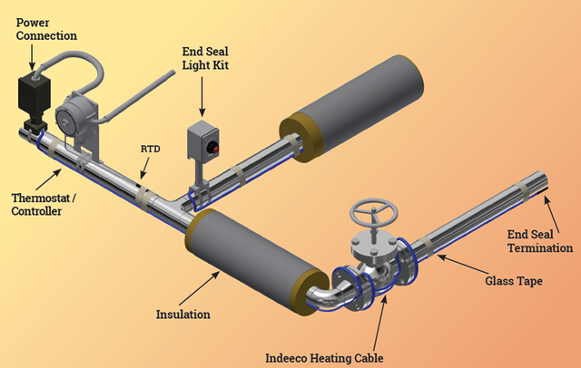
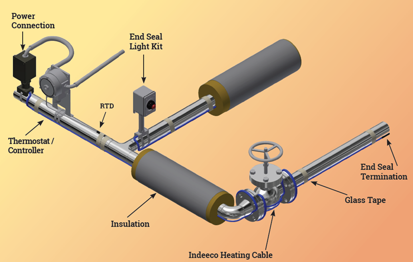
A typical heat-trace circuit
Key Features & Benefits
- Self-regulating cable cannot burn itself out — the polymer core drops its own output as the pipe warms and raises it as the pipe cools, so the cable can be overlapped at valves and supports and left energized without the hot-spot failure that kills constant-watt cable. Forgiving to install and hard to cook — the reason self-regulating cable dominates freeze protection.
- One line from freeze protection to 900°F process heat — four stocked self-regulating cables cover the 150–375°F band and mineral-insulated cable carries the high-temperature jobs, so a single supplier spans roof de-icing, process maintenance, and high-exposure pipe (the bands are in the specifications). Match the cable to the temperature without changing vendors.
- Cut, install, and stock the same day — self-regulating cable is field-cut to length, terminated with a stocked accessory kit, and shipped same-day on before-noon orders — no factory fabrication wait for the common freeze-protection job. The pipe that has to be protected before the next cold snap gets cable now.
- iHeat HRSG makes the tube its own heater — on steam-drum sample lines the impedance system energizes the process tube directly, collapsing the traced bundle to a single circuit with far fewer joints and a fraction of the power draw — and it retrofits onto the tube already installed. Less power, less cable tray, fewer failure points on the hardest lines to heat.
- Built for the hazardous area, not adapted to it — the self-regulating cables carry FM / CSA / UL (CE on most) approvals with published T-ratings, and matching Division 1/2 thermostats and controllers extend the system into classified space. The area classification is designed in, with the paperwork the inspector expects.
Specifications
- Operating principle
- Electric resistance heat tracing — a heating cable is run along the outside of a pipe, tank, or instrument-tubing run, then covered with thermal insulation. The cable’s output replaces the heat the pipe loses, so the contents are held at a maintain temperature or kept from freezing. Self-regulating cable uses a semiconductive polymer core that raises and lowers its own output with pipe temperature — warmer pipe, less power — which optimizes energy use and lets the cable be overlapped without burnout.
- Cable types & output
- Four self-regulating cables span the maintain range (see the table below): CRG® (freeze protection of metal & plastic pipe plus roof & gutter de-icing, 150°F maintain), LSR® (freeze protection & process maintenance of metal & plastic pipe, 150°F), MSR® (metal pipe & tanks, 250°F maintain), and HSR® (metal pipe & tanks, 375°F maintain). For higher temperatures, mineral-insulated (MI) constant-watt cable and iHeat impedance heating extend the line (below). Self-regulating cable is cut to length and terminated in the field.
Self-Regulating & MI Cable Selection
| Cable | Maintain | Exposure | Output (W/ft @ 50°F) | Approvals |
|---|---|---|---|---|
| CRG® | 150°F (65°C) | 185°F (85°C) | 3, 5, 8, 10 | FM, CSA, UL |
| LSR® | 150°F (65°C) | 185°F (85°C) | 3, 5, 8, 10 | FM, CSA, UL, CE |
| MSR® | 250°F (120°C) | 366°F (185°C) | 5, 10, 15 | FM, CSA, CE |
| HSR® | 375°F (190°C) | 450°F (232°C) | 5, 10, 15, 20, 25, 30 | FM, CSA, CE |
| MI (MIHT) | 900°F (482°C) | 1100°F (593°C) | up to 50 | IEEE-tested |
- Mineral-insulated (MI) cable
- Type MIHT mineral-insulated (MI) cable — resistive conductors in highly compressed magnesium-oxide insulation under a fully annealed, hand-formable Alloy 825 sheath — serves the high-temperature end: maintain to 900°F (482°C), exposure to 1100°F (593°C), 120–600 V, and power output up to 50 W/ft. It is constant-wattage (not self-regulating), totally inorganic so it will not age out, and is factory-fabricated to a specified hot- and cold-section length in one- or two-conductor Form A/B/C builds. Typical use: process-pipe heating, snow melting, tank & vessel heating, and high-exposure service.
- iHeat impedance tube heating
- iHeat HRSG is Indeeco’s patent-pending impedance heating system for HRSG / cogen steam-drum sample lines: rather than tracing a cable alongside the tube, the sample tube itself becomes the heater as current passes through it. A single circuit can serve all the sample and chemical-feed lines (HP / IP / LP) on a heat-recovery steam generator, with even, continuous heat and far fewer joints and connections. Indeeco cites winter operating power of 2.9 kW for impedance vs. 9.8 kW for conventional heat tracing on a representative system, and the existing installed tube can be fitted for impedance heat as a retrofit.
- iHeat pre-traced tubing
- iHeat pre-traced tubing ships weatherproof on long spools, ready to install and free of tube unions, for small-bore instrument and process tubing. Build styles: jacket-only (JTB), pre-insulated (STB), steam-traced (LTB light / HTB heavy), and electric-traced (ETBL 40–80°F, ETBM 40–250°F, ETBH 40–375°F maintain). Process tube is 1/8″ through 3/4″ OD in 316/316L stainless (seamless ASTM A-269/A-213), Alloy 825, or PFA. Used for impulse / sample / chemical-feed lines and dew-point maintenance on gas streams.
- Cable construction
- Self-regulating cable is built on 16 AWG nickel-plated copper bus wires with a radiation cross-linked (CRG / LSR) or modified-fluoropolymer (MSR / HSR) polymer heater core, an insulating jacket, and a tinned-copper braid (the braid is the equipment ground and is required for the listing). Cross-section is roughly 1/2″ W × 1/4″ H. MI cable is conductors in compacted MgO under an Alloy 825 sheath, where the low-resistance sheath is the ground path.
- Jacket & chemical resistance
- Standard outer jacket is flame-retardant, UV-stabilized polyolefin. Two over-jackets are optional on the self-regulating cables: a modified-polyolefin jacket (protects against aqueous inorganic chemicals) and a fluoropolymer jacket (protects against organic and corrosive chemicals). Match the jacket to the chemical exposure in the insulation space.
- Maintain temperature
- Continuous maintain temperature by cable: CRG / LSR 150°F (65°C), MSR 250°F (120°C), HSR 375°F (190°C). MI cable maintains to 900°F (482°C). See the cable-selection table below.
- Exposure temperature
- Maximum exposure (power-off) temperature by cable: CRG / LSR 185°F (85°C), MSR 366°F (185°C), HSR 450°F (232°C, intermittent). MI cable to 1100°F (593°C). Exposure is the temperature the de-energized cable can survive — check it against any steam-out or process upset, not just the maintain setpoint.
- Power output (W/ft)
- Nominal output at 50°F on insulated metal pipe: CRG / LSR 3, 5, 8, 10 W/ft; MSR 5, 10, 15 W/ft; HSR 5, 10, 15, 20, 25, 30 W/ft; MI cable up to 50 W/ft. CRG rates 10/12/16/18 W/ft in snow & ice for roof & gutter de-icing. Derate self-regulating output 35% on plastic pipe and use the aluminum-tape install method.
- Bend radius & install temperature
- Self-regulating cable installs down to −40°F (−40°C) with a minimum bend radius of 1-1/8″, and can be overlapped without burnout — a property of the self-regulating core that lets it be doubled back at valves and supports.
- Supply voltage
- 120 V and 208–277 VAC on the self-regulating cables; 120–600 V on MI cable. Apply the catalog power-adjustment factor when running self-regulating cable at 208 V or 277 V.
- Circuit length & breaker sizing
- Maximum circuit length per cable runs from the catalog tables and depends on start-up temperature and breaker size (15 / 20 / 30 / 40 A) — lengths to 660 ft (200 m) on the lighter self-regulating cables. Self-regulating cable ships ±5% of label on spools to 1000 ft (250 ft minimum order, cut to length without fee). MI cable is fabricated to the exact hot- and cold-section length ordered.
- Ground-fault protection
- Ground-fault circuit protection is required on every heat-trace branch circuit — typical minimum trip level 30 mA. Thermal-magnetic breakers are recommended to reduce nuisance tripping; the catalog circuit-length tables are based on Type QO / QOB device trip characteristics.
- Thermostats
- Mechanical line- or ambient-sensing thermostats: HTTS-A / HTTS-L (ordinary area) and HTTS-EPA / HTTS-EPL (Class I, Division 1 & 2, Groups B, C, D). All are SPDT, 22 A switching at 120–480 V, high-accuracy. A heavy-duty single-stage liquid-filled thermostat covers a −30 to 100°F range. Stocked for same-day shipment.
- Electronic controllers & panels
- Electronic control scales from a single circuit up: the HTCTRLR microprocessor controller (30 A SSR, 85–280 V, Class I Div 2 Groups B/C/D) with ground-fault alarm & trip and communications, in single (-1) or dual (-2) circuit; and the MasterTrace multi-circuit control panel (30 A SSR, 280 V max, Class I Div 2 Groups A–D) in 5- (-5), 10- (-10), or custom-circuit builds. Single, dual, and multi-loop line- and ambient-sensing monitoring systems are available for ordinary and hazardous areas.
- Connection accessories
- A full third-party-required accessory set ships from stock: power-connection kits, pipe stand-offs, splice/tee connections, plain and lighted end seals, application and aluminum-foil tape, pipe straps, caution labels, and an armored RTD cable with cord grip. Every cable requires at minimum a power connection and an end-seal termination to meet the third-party listing.
- Area classification & T-rating
- Self-regulating cables are approved for ordinary and Division 2 hazardous areas with a T-rating by output: LSR 3/5/8 W/ft = T6, 10 W/ft = T5; MSR = T3; HSR = T3. Hazardous-area thermostats (HTTS-EP) and controllers extend the system into Class I Division 1/2 locations. Supply the area Class / Division, Group, and required T-code with the order.
- Approvals & listings
- Third-party approvals by cable: CRG — FM, CSA, UL; LSR — FM, CSA, UL, CE; MSR — FM, CSA, CE; HSR — FM, CSA, CE. MI heating units are factory-fabricated and tested to IEEE standards. Ground-fault protection on every branch circuit is the installer’s responsibility per the catalog and local code.
- Stock & lead time
- Self-regulating cable, stock controls, and accessories ship same day on orders placed before noon Central. MI cable, iHeat tubing, and impedance systems are engineered and fabricated to the application; no published price list, quote-only. Lead times typically run about 3 to 14 weeks depending on configuration, hazardous-area documentation, and code-stamp requirements.
Common Applications
- Freeze protection of metal and plastic process and water pipe
- Process temperature maintenance on metal pipe and tanks (to 375°F self-regulating)
- High-temperature process-pipe and tank/vessel heating with mineral-insulated cable (to 900°F maintain)
- Roof & gutter de-icing and snow melting
- HRSG / cogen steam-drum sample-line and chemical-feed-line freeze protection — iHeat HRSG impedance heating
- Freeze protection and dew-point maintenance of small-bore instrument impulse, sample, and chemical-feed tubing — iHeat pre-traced tubing
Design & Selection Considerations
- Pick the cable by maintain AND exposure, not just maintain — a cable rated for your maintain temperature can still be destroyed by a steam-out or process upset that exceeds its exposure rating. Check both bands against the worst de-energized temperature the pipe can see (the values are in the specifications). Exposure temperature is what fails a cable that was “rated” for the job.
- Insulation is part of the heater — size the cable to it — heat-trace output is sized to the pipe’s heat loss, which is set by the insulation type and thickness, the pipe diameter, and the minimum ambient. Cable on bare or wet insulation cannot hold setpoint. Use the input form to give us the insulation and the minimum ambient, and keep the lagging dry and intact.
- Ground-fault protection is mandatory, and it is the system’s safety net — every heat-trace branch needs ground-fault protection (typically 30 mA trip); thermal-magnetic breakers cut nuisance trips. A wet end seal or damaged jacket shows up first as a rising ground-fault current. Wire the GFEP in — it is both code and your earliest leak indicator.
- Derate on plastic pipe and respect the circuit-length limit — plastic pipe takes a 35% output derate and the aluminum-tape install method, and every cable has a maximum circuit length that shrinks as start-up temperature drops and breaker size falls. Exceed it and the far end never comes up to temperature. Confirm pipe material, start-up temperature, and breaker size before fixing the run length.
- Terminate it properly or void the listing — a heat-trace circuit is only listed when it carries at least a proper power connection and end-seal termination; the braid must be grounded. Field shortcuts on terminations are the most common moisture-ingress and code-failure point. Budget the stocked accessory kit into every run — it is not optional hardware.
- Match the control to the duty — ambient, line, or monitored — simple freeze protection runs on an ambient- or line-sensing thermostat; process maintenance and critical lines want an electronic controller with ground-fault alarm and communications, or a multi-circuit MasterTrace panel that monitors every loop. Decide whether you need to know a circuit failed before you pick the control.
- Megger before and after install — the listing and IEEE practice call for an insulation-resistance (megger) check at commissioning and as part of periodic inspection; the inspection report records the megger value, supply voltage, and ground-fault current. A baseline megger reading is what later tells you a circuit is degrading before it trips.
To select the right Indeeco heat-trace system:
Use the input form to send your pipe diameter and material (metal or plastic), pipe length, the insulation type and thickness, indoor / outdoor location, the maintain temperature and the maximum exposure temperature, the minimum ambient, the operating voltage (120 / 208 / 240 / 277 V), the control method (line- or ambient-sensing thermostat or electronic controller), and the area classification — Class, Division, Group, and T-rating — plus the number of valves, flanges, tees, and pipe supports in the line, and we’ll select the cable, size the circuit, and spec the right Indeeco controls and accessories.
Electric Heating Application Sheet ›Talk to an engineer directly — Scott Prater, Principal · 917-580-0878 · scott@pratertechnical.com
Specifications compiled by Prater Technical Partners from Aspeq Heating Group product datasheets.