Product Overview
An impedance heating system turns the process pipe into its own heating element: low-voltage AC from a custom transformer drives current through the pipe wall, which generates heat by resistance, skin/proximity effect, and hysteresis — uniformly along the whole pipe, without hot spots. With no element or dielectric in the heated zone, there is nothing to burn out and the temperature ceiling is set by the pipe and fluid rather than the heater — from freeze protection up to high-temperature gas maintain. Choose impedance to heat a long run of conductive metal pipe uniformly — freeze protection, viscosity maintenance, cold-start, or temperature rise on asphalt, heavy oils, chemicals, food lines, and process gas. It is a designed system (transformer, control panel, terminal plates, isolation kits, sensors); the pipe and insulation are customer-supplied.
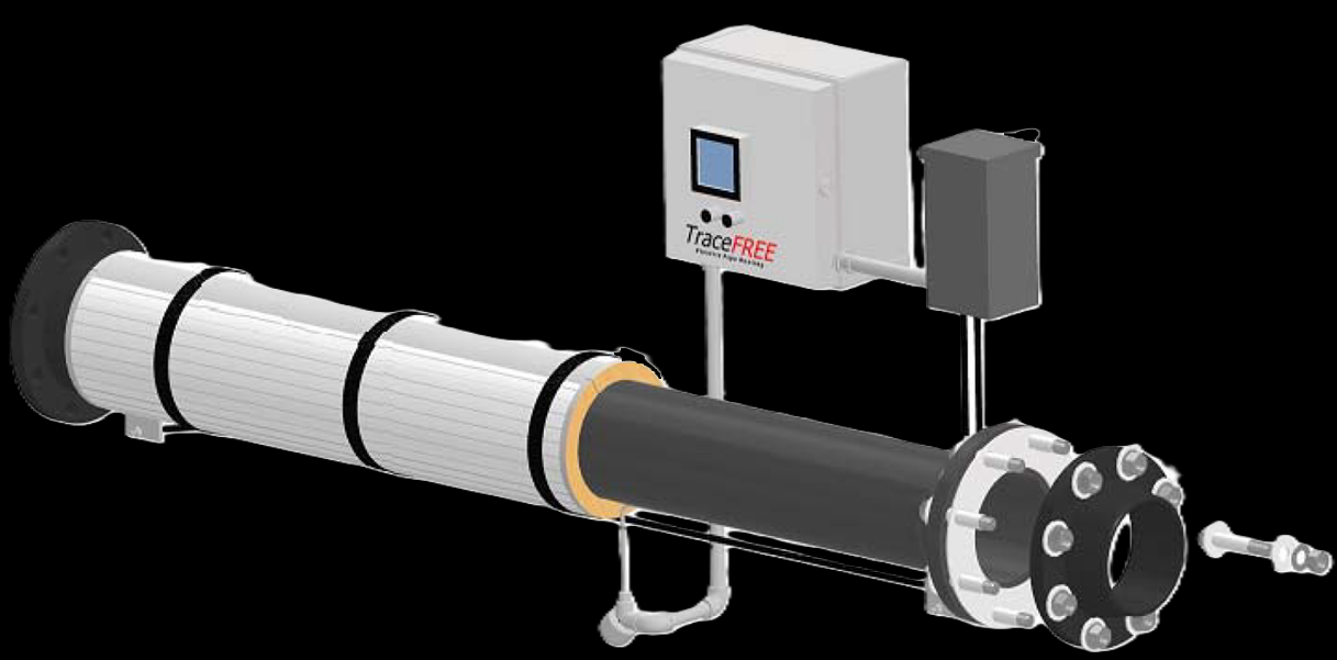
Key Features & Benefits
- The pipe is the heater — nothing to burn out — because the process pipe itself generates the heat, there is no resistance tape, cable, or element to fail, so the burnouts and replacement cycles of conventional tracing simply go away. Installations have run for 40+ years; many operate unattended with virtually no maintenance.
- Even heat with no hot spots — the whole pipe surface heats uniformly along its length and around its circumference, so temperature-sensitive materials — asphalt, chocolate, heavy syrups — are kept fluid without local scorching. The right answer when conventional tracing would cook the product against the wall.
- Reaches temperatures other pipe heating cannot — the heater puts nothing in the heated zone that limits it, so the temperature ceiling belongs to the pipe and the fluid — making impedance often the only viable choice for high-temperature pipeline heating. When the maintain temperature climbs past where heat-trace cable stops, this is the technology that keeps going.
- Inherently safe at the pipe — the energized pipe runs at low voltage — well below the level OSHA and the NEC tie to perceptible shock — and redundant over-temperature and ground-fault protection back it up. Personnel-safe by design, with the live components still guarded.
- Simple to install and own — a few basic components make up the whole system, and it can usually be installed without disturbing most of the existing pipe insulation; energy goes straight into the pipe, and routine maintenance is essentially eliminated. Low installed cost, low operating cost, and Indeeco single-source design plus start-up.
Specifications
- Operating principle
- The process pipe itself is the heating element. A custom step-down transformer applies low-voltage AC across the heated length of pipe, so the pipe wall acts as the resistor and heat is generated over its entire length and circumference. Three effects combine: resistance (Joule) heating in the pipe wall, skin and proximity effect (current concentrates at the outer surface, drawn by the field of the secondary cable), and hysteresis from the reversing magnetic flux in the magnetic pipe material. Used to maintain temperature (pipe tracing), raise temperature between inlet and outlet, or cold-start a static, viscous material so it can be pumped.
- Pipe size range
- ¾″ to 24″ IPS for carbon steel (specify IPS size and schedule), and up to 36″ for alloy pipe (specify outside diameter and wall thickness). The pipe is normally customer-supplied and installed; the heating system is designed around its size, schedule, and material.
- Pipe material
- Any sufficiently resistive, magnetic-or-suitable pipe alloy: carbon steel, stainless steel, nickel, Incoloy, Inconel, Monel, Hastelloy, and Duranickel. Copper, aluminum, and other highly conductive metals cannot be used, and non-conductive pipe such as plastic is unsuitable. Mixed piping in one circuit causes uneven heating, so the heated run must be a single specified material and schedule.
- Heated length
- Single-circuit heated lengths to roughly 1,000 ft are standard (longer single circuits are possible depending on pipe size, material, and heat loss); very short runs of a few feet are also served but are often impractical. Long runs may be split into multiple systems. An accurate measured pipe length is critical — an estimated length yields a system that does not perform as designed.
- Electrical connection
- Two connection schemes. End-point (end-feed) — cable attached at each end of the run; best for complex layouts with branches or “tees,” with no need to electrically balance the circuit. Mid-point (center-feed) — cable fed at the electrical mid-point; the pipe ends do not require electrical isolation, and roughly twice the length can be heated at the same secondary voltage. Mid-point suits straight or simple runs (and is also used for highly conductive fluids, since the ends need no isolation).
- Transformer
- A custom step-down, single-phase dry-type system transformer, sized to the application’s KVA and furnished in a ventilated NEMA 3R enclosure (NEMA 4, stainless, copper-free aluminum, fiberglass, or epoxy-encapsulated windings available for corrosive service). It carries multiple voltage taps for field fine-tuning to the actual pipe length, insulation, or a future setpoint change. Transformer skin temperature stays within OSHA limits, so it can be located within reach of personnel.
- Operating voltage
- Secondary output is 1 to 30 V (30 V maximum per NEC), with many systems operating at 10 V or below — well under the 50 V threshold OSHA and the NEC associate with shock and heart-fibrillation risk, so the energized pipe is inherently safe to personnel. The transformer is a passive device and cannot generate a voltage spike on its own; system fusing trips on excessive power.
- Temperature range
- From below freezing (freeze protection) up to high-temperature gas maintain. The current 881-series brochure states a wide range “from ambient to >1,000°F, only limited by pipe and fluid,” while the 881-series product page cites maintaining gas temperatures up to 1,600°F. Because there are no dielectric components in the heated zone, the maximum is set by the pipe alloy and the fluid thresholds, not by the heater — documented installations have heated pipe to 1,200°F (process air) and 1,300°F (magnesium chloride). Confirm the maximum for your pipe alloy and fluid with the design.
- Heat uniformity
- Heat is generated by the full pipe surface, so it is distributed uniformly along the length and around the circumference, without hot spots. That even, low-intensity delivery is what makes impedance suitable for temperature-sensitive materials (asphalt, chocolate, heavy syrups) that conventional tracing tends to scorch. With SCR control, regulation to ±1°F is achievable.
- Pipe (sheath) temperature limiting
- Pipe (sheath) temperature is held by a control-limited approach per IEEE 844.3 Annex B3.3: a process sensor controls the maintain temperature and a second, independent sensor drives an over-temperature cut-off that removes power on an elevated-temperature fault. This same control-limited method establishes the temperature (T-code) classification on hazardous-area systems.
- Terminal plates & cable
- Current passes from the secondary cable to the pipe through weld-on terminal plates — stainless steel or copper-plated carbon steel, sized and shaped for the pipe, with crimped or bolted lugs for field cable attachment (perforated plates for high-temperature service). The secondary cable is selected for the system current; Indeeco can supply copper cable with the matching terminations.
- Electrical isolation
- To keep each circuit electrically uniform end-to-end, flange isolation kits (dielectric gasket, non-conductive bolt sleeves, and washers) are installed at tees, grounded equipment, and bulkheads so stray currents and branch-circuit division are prevented. Pipe supports are isolated as well (fluoropolymer pads, polymer inserts, or non-metallic sleeves). Grounded instrumentation on the heated line must be electrically isolated with flange and jumper kits. Standard isolation kits suit process temperatures to 450°F; common gasket materials are aramid fiber and mica.
- Temperature sensors
- Two weld-pad-mounted thermocouples sense pipe-surface temperature — one for the process controller and one for the high-limit / over-temperature controller; both must be the ungrounded type. Standard sensor is Type J; Type K thermocouples or RTDs are available. The pipe-surface temperature tracks the fluid temperature closely. (Fiber-optic temperature cable can be added to monitor the whole line and locate cold sections.)
- Thermal insulation
- Thermal insulation on the heated pipe is customer-supplied and installed and is normally required for energy efficiency and personnel protection — fiberglass for low temperatures, calcium silicate above 300°F; an existing jacket is designed around its R-value. The system can be installed without disturbing most existing insulation. Heating without insulation is possible but unusual.
- System rating (KVA)
- Each system is sized in KVA from the pipe size and material, heated length, heat-loss (insulation type / thickness, ambient, wind), and the maintain / heat-up duty — computed by Indeeco’s ImpedancePRO thermal and electrical design program. Documented systems range from about 1.5 KVA (a short sanitary chocolate line) to 120 KVA (high-pressure test-air heating); larger or multi-zone designs combine several systems.
- Temperature control
- Standard control is an on/off contactor panel with an electronic process controller (digital indication) and an independent electronic high-limit / over-temperature controller with manual or auto reset. SCR proportional control (phase-angle fired, single-phase, with soft-start current limit) gives precise regulation to ±1°F. The full range spans simple discrete control through multi-loop, PID, PLC, and HMI options.
- Control integration
- Beyond on/off and SCR, panels add remote communication, data logging, multiple alarms, remote signal inputs / interlocks, voltmeters, and ammeters; contactor, SSR, and 0–100% SCR switching are offered to suit the duty. Panels can serve a single discrete circuit or coordinate several impedance systems. Equipment ground-fault protection continuously monitors for an energized-pipe-to-ground short and shuts the system down automatically.
- Enclosures
- Standard control panel is a NEMA 12 enclosure; the transformer is NEMA 3R. NEMA 4 and NEMA 4X (washdown / corrosive) panels and a NEMA 7 cast-aluminum (with optional purge) option are available; transformers are offered in stainless, copper-free aluminum, or fiberglass enclosures for special environments.
- Hazardous-area rating
- Impedance systems can be installed in Class I and Class II, Division 2 hazardous locations. NEC Article 427 covers the requirements for impedance (skin-effect) pipeline heating, with ANSI/IEEE 844 referenced for hazardous-location detail; the sheath-temperature (T-code) classification is set by the IEEE 844.3 control-limited method. Provide the area Class, Division, Group, and required ignition-temperature code with the inquiry.
- Codes, standards & safety
- Designed and built to NEMA and UL standards, and engineered per NEC (Article 427), NFPA 70E, CEC, and IEEE 844 guidelines for impedance heating. Redundant safeguards — independent over-temperature cut-off and automatic ground-fault shutdown — protect the system; live components are guarded against incidental contact even though the pipe operates below 50 V. The user is responsible for complete electrical isolation of the heated line and for following the IOM and local code.
- Build & lead time
- Custom build-to-order — no published price list, quote-only. Lead times typically run about 3 to 14 weeks depending on configuration, hazardous-area documentation, and code-stamp requirements.
Common Applications
- Freeze protection and viscosity maintenance on long process pipelines — oil & gas, refineries, petrochemical
- Cold-start heating of static viscous materials so they can be pumped — asphalt, coal-tar pitch, heavy fuel oils, molasses
- Temperature-sensitive food and ingredient lines held at setpoint — chocolate, sweeteners, sugars (often sanitary stainless tubing)
- Temperature-rise heating of corrosive liquids and high-temperature process gases between inlet and outlet
- High-temperature, high-pressure test-air and process-air heating — power, aerospace, test stands
- Sulphur, molten salt, molten lead, wax, and other high-temperature process-fluid lines
Design & Selection Considerations
- Isolate the entire heated line — one miss defeats the circuit — the heated pipe must be electrically isolated from every ground: tees, pipe supports, bulkheads, and grounded instrumentation all need isolation kits, jumpers, or non-conductive support inserts. A single missed point becomes a stray-current path or a ground-fault trip. Walk the full line before start-up; the start-up procedure will expose any isolation that was missed.
- Measure the pipe length — do not estimate it — the impedance design is driven by an accurate pipe length, size, schedule, and material; an estimated length or mixed piping in one circuit yields uneven heating or a system that misses its design temperature. Use the input form to give us the as-built run, not a drawing dimension.
- Pick the connection scheme to the layout — end-point connection handles complex layouts with tees without electrical balancing; mid-point heats roughly twice the length at the same voltage and needs no end isolation, which also suits highly conductive fluids — but it wants a straight or simple run where the electrical mid-point is clear. The piping geometry, not preference, picks end-point vs mid-point.
- Conductive fluid is not a shock or current-loss concern — skin effect drives the current to the outer pipe surface and pipe resistivity is far lower than even the most conductive fluid, so little current flows on the inside; for very conductive fluids a mid-fed design removes the need to isolate the ends. The fluid does not carry the heating current — the pipe wall does.
- Keep grounded objects off the heated pipe — a scaffold, a leaning pipe, or any grounded object touching the insulation or pipe can trigger a ground-fault trip or cause a current loss that lets a section run cold. Maintain clearance and insulation integrity over the life of the line.
- Shut down and disconnect before welding on the pipe — welding on an energized impedance line can damage the transformer and control panel; power off and the secondary cables disconnected is the rule for any line maintenance. Treat the heated pipe as a live circuit during any hot work.
- Plan the site scope — impedance is a system, not a drop-in — Indeeco supplies the transformer, control panel, cable, terminal plates, isolation kits, and sensors; the pipe and insulation are yours, and installation needs an accredited electrical team plus pipe / insulation crews and weld equipment for the terminal plates and thermocouples. Budget the install and commissioning, not just the hardware — factory start-up is a recommended option (and extends the warranty).
To design the right Indeeco impedance heating system:
Use the input form to send your pipe diameter and schedule, pipe material, and accurate heated length, the insulation type and thickness, the minimum / maximum ambient (and wind exposure if outdoor), and the duty — maintain temperature, or the inlet / outlet temperatures and flow rate for a temperature rise, or the material properties and required heat-up time for a cold start. Note any hazardous-area classification (Class, Division, Group, T-code), the available power (volts / phase), and the control type — and include a P&ID or isometric piping layout. We’ll run the ImpedancePRO design and spec the transformer, control panel, and isolation hardware for your line.
Electric Heating Application Sheet ›Talk to an engineer directly — Scott Prater, Principal · 917-580-0878 · scott@pratertechnical.com
Specifications compiled by Prater Technical Partners from Aspeq Heating Group product datasheets.