Product Overview
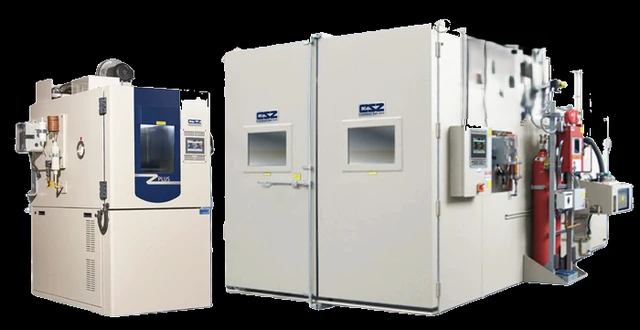
A CSZ battery test chamber is a temperature/humidity chamber re-engineered around the assumption that a cell may vent, ignite, or go into thermal runaway during the test. It pairs the usual thermal envelope — −70°C to +190°C, optional humidity — with a layered safety package — non-sparking fans and a door interlock at baseline, building up through gas-detection interlocks, fresh-air or inert purge, a heated pressure-relief port, CO₂ suppression, and temperature-limited heaters — matched to the cell chemistry and abuse scope by the EUCAR hazard-severity scale. This is a distinct class of chamber, specified as such from the start — you do not retrofit a standard chamber for battery abuse testing. It sizes from a benchtop reach-in for cells to a walk-in room for full packs and integrates with cyclers and data acquisition.
Key Features & Benefits
- A distinct class — not a retrofitted standard chamber — the chamber is designed from the start around a cell that may vent or ignite, so the containment, venting, gas detection, and interlocks are engineered in, not bolted on. You specify a battery chamber as such; you do not adapt a general-purpose box for abuse testing.
- Safety scaled to the credible worst case — the package is sized to the hazard you intend to run, so a benign cycling job is not burdened with full explosion containment, and an abuse program is not under-protected. The protection matches the hazard, by design.
- Deep cold on a single compressor — the patented Tundra and Tundra II systems reach −45°C and −50°C on one compressor, which the brochure ties directly to lower electrical and maintenance cost. Cold-soak capability without the operating bill of a cascade you do not need.
- Built to integrate with the rest of the test stand — the chamber is designed to interface with the cycler and the data system, so the thermal environment is one part of a complete, instrumented test. It drops into your test architecture rather than standing apart from it.
- Sized from the cell to the full pack — the same safety philosophy carries from a benchtop reach-in for cells to a walk-in room for full packs, so the program can grow without changing vendors or approach. One safety design language across the size range.
Specifications
- Operating principle
- Electric resistance heating, mechanical refrigeration, and (on humidity models) a humidification system condition the air around the test article — the same thermal core as a standard temperature/humidity chamber, re-engineered around the assumption that a cell may vent, ignite, or go into thermal runaway during the test. The safety system, not the temperature range, is what defines this class.
- Configuration & access
- Built to the test requirement — reach-in for cells and small modules through to walk-in rooms for full battery packs. Each chamber is configured to the specific test and can be interfaced with battery cyclers, data acquisition, and monitoring systems for an integrated test setup.
- Temperature range
- −70°C to +190°C (−94°F to +375°F) across the line, by refrigeration tier (below).
- Humidity range
- Optional, as low as 10% to 95% RH on humidity-equipped builds.
- Refrigeration system
- Tiered to the required low: single-stage to −34°C, Tundra® (single compressor) to −45°C, Tundra® II (single compressor) to −50°C, and cascade to −70°C. The Tundra single-compressor systems reach deep cold on one compressor, which lowers the operating and maintenance cost that the compressors otherwise dominate.
- Workspace volume & sizes
- From small benchtop units to large walk-in rooms, sized to the cell, module, or pack under test; configured per application.
- Thermal-runaway safety system
- Layered, and matched feature-by-feature to the hazard level. A baseline build carries non-sparking fan blades / blower wheel, a product over-temperature limit with alarm, and an electronic safety door interlock; as the hazard scope rises, the package adds (per the EUCAR-to-safety mapping) an audible/visual safety light stack, a fresh-air blower or N₂/dry-air purge to clear gases before the door opens, a gas monitor (H₂, CO — O₂ and others available) interlocked to shut the chamber down on detection, a heated pressure-relief port (a ceiling port that re-seats after the event and stays heated so it cannot freeze shut), CO₂ fire suppression (Firetrace-triggered, to manage rather than stop runaway), and at the top tier temperature-limited sheath heaters held below the ignition point of vent gases (standard nichrome wire can reach +540°C), a reinforced (16-ga) test space, an over-pressure burst disc with sensor, and secondary door restraint. Externally mounted lighting removes an internal spark source. Options across the range include intrinsically-safe sensor barriers (recommended where hydrogen may be present), high-pressure water-mist suppression, and a customer-matched fire package. Specify the hazard level and the features follow it.
- Hazard tiering
- The build is tiered to the cell chemistry and abuse scope by the EUCAR / FreedomCAR hazard-severity scale — from level 0 (no effect) up through rupture and explosion at the top of the scale — with a published equipment map setting which safety features are standard versus optional at each level, so the package matches the credible worst case rather than being over- or under-built.
- Standards & protocols
- Battery-abuse and reliability methods — the master CSZ references include IEC 62660-2, SAE J2464, and the UL battery series; the chamber is built to the methods your program calls out.
- Controller & software
- Touchscreen controller storing multi-step temperature/humidity profiles with data logging, audit trail, and email/text alarms, over Ethernet/TCP-IP for remote monitoring; gas monitors and safety interlocks tie into the control sequence. Specify cycler / data-acquisition integration up front.
- Build & lead time
- Each battery chamber is configured or custom-engineered to the test and hazard scope; CSZ chambers are quote-only with a build lead time that scales with size and the safety package. Lead time is confirmed at quotation.
Common Applications
- Lithium-ion, NiMH, and lead-acid cell, module, and pack testing — from small cells to large packs
- Temperature cycling, soak, and humidity conditioning of batteries for automotive and EV programs
- Reliability and abuse testing to battery-system standards (IEC 62660-2, SAE J2464, UL battery methods)
- Energy-storage, telecommunications, defense, and computing battery qualification
- Integrated chamber-plus-cycler test stands with combined data acquisition
Design & Selection Considerations
- Tier the safety package to the hazard — over- and under-building both cost — use the EUCAR / FreedomCAR severity levels to decide how far to go: a level-0/1 cycling study does not need full explosion containment, while a level-5+ abuse test does. Use the input form to tell us the chemistry and the abuse scope and we build to it. The single most important decision on a battery chamber is how hard it has to fail-safe.
- A spark source is the difference between a vent and a fire — a cell can vent flammable gas without igniting if no ignition source is present — which is exactly why gas detection, non-sparking fans, and external lighting matter, and why abuse protocols sometimes add a spark source deliberately. Decide whether your test intends ignition, because the venting and suppression design follows from it. Plan for the gas before you plan for the flame.
- Purge the gas before anyone opens the door — vent gases are the hazard to personnel after an event, not just during it; the fresh-air exchange and door interlock exist to clear the chamber and keep it shut until it is safe. The post-event sequence is part of the safety case, not an afterthought.
- Inert atmosphere contains — it does not prevent runaway — an N₂ or CO₂ inert atmosphere removes oxygen and helps contain an event, but it does not stop a cell from going into thermal runaway; treat it as containment, not prevention, and design the venting and suppression accordingly. Know what each safety feature does and does not do.
- Account for the pack weight in the floor and the structure — a full battery pack is heavy and the reinforced floor exists for that reason; the article-plus-fixturing static weight has to be within the chamber’s rated capacity, which on a large pack points to a reinforced reach-in or a walk-in. Confirm the dead load early — it can decide reach-in vs walk-in.
- Integrate the cycler and data system from the start — powered abuse and life testing run the cell from a cycler while the chamber holds temperature; design the cabling, ports, and data interface up front so the chamber and the cycler work as one instrumented stand. Specify the integration with the chamber, not after it ships.
To spec the right CSZ battery test chamber:
To configure the right chamber, the application drives every choice — so the more of this you can give us up front, the tighter the quote:
- the test standard or protocol you are working to (ICH Q1A / Q1B Option 2, IEC 62660-2, SAE J2464, a UL battery method, an internal spec);
- the test article — size, weight, quantity, and (for powered tests) the heat it dissipates;
- the required temperature and humidity range and how tightly you need them held;
- whether the work is regulated (21 CFR Part 11 audit trail, IQ/OQ/PQ qualification) — and, for battery work, the hazard scope (cell chemistry and the abuse you intend to run);
- your site — available power, water, drainage, doorway and ceiling clearance, and floor loading.
Talk to an engineer directly — Scott Prater, Principal · 917-580-0878 · scott@pratertechnical.com
Specifications compiled by Prater Technical Partners from Cincinnati Sub-Zero published product specifications.