Product Overview
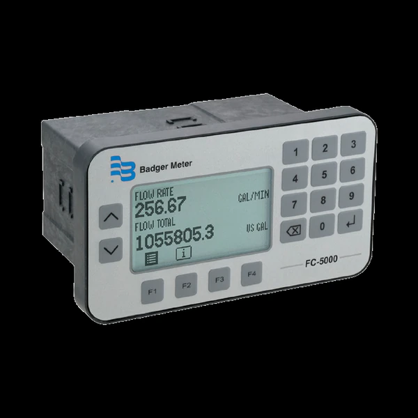
The FC-5000 BTU Monitor turns an Impeller flow point into a complete hydronic energy meter: it pairs one Data Industrial flow input with two temperature inputs (supply and return) and computes energy / BTU rate and total to EN 1434 alongside flow rate and total. The temperature channels read Pt 100 / 1000 Ω RTDs or Type II thermistors; energy accuracy on a low-ΔT loop lives in that matched pair, and the loop fluid’s properties are set at commissioning so a glycol mix reads true BTU. A 128 × 64 backlit graphical display with a full numeric keypad, Modbus / BACnet over RS-485, order-time scaled outputs, relays and six digital I/O channels make it a flexible energy and monitoring station, in a panel cutout or a NEMA 4X / IP67 field enclosure. For flow-only monitoring on the same platform — with a second flow channel in place of the temperature pair — see the FC-5000 Flow Computer.
Key Features & Benefits
- Turns a flow point into a hydronic energy meter — one impeller flow input plus a supply / return temperature pair computes energy / BTU rate and total to EN 1434 — the function a flow sensor cannot do on its own
- Two RTD / thermistor temperature inputs — two independent channels read Pt 100 / 1000 Ω RTDs (2-, 3- or 4-wire) or Type II thermistors for the supply and return legs
- On the building network — Modbus RTU / ASCII or BACnet over RS-485 puts energy, flow and both temperatures on the plant or facility network — up to 255 units on one daisy-chain — and a Mini-B USB handles field updates
- Big backlit graphical LCD — a 128 × 64-pixel LED-backlit display with softkeys and a numeric keypad shows energy or flow, single or dual view
- Relays, outputs and I/O ordered to the job — two relays, two scaled analog or frequency outputs and six isolated digital channels for remote reset — the set is specified at order time
- Panel or NEMA 4X field mount — a panel cutout for the control room or a NEMA 4X / IP67 enclosure for the field
Specifications
- Function
- Microprocessor-driven industrial energy / BTU monitor — computes hydronic energy from one impeller flow input plus two temperature inputs, and totalizes and displays flow alongside it
- Meter & sensor compatibility
- Pairs with the full line of Data Industrial / Badger Meter impeller flow sensors and temperature sensors
- Measured & displayed parameters
- Energy / BTU rate and total, flow rate and total, mass flow rate and total, and both temperatures; a sensor-data screen shows raw and calculated values plus relay, output and I/O status
- Flow-meter input
- One flow channel plus two temperature inputs — the BTU build trades the second flow channel for the temperature pair; 0.3 Hz–10 kHz; square-wave 0–30V pulse (2.5V threshold) or zero-centered sine (45 mV threshold), configurable debounce
- Temperature inputs
- Two channels — 2-, 3- or 4-wire platinum 100 / 1000 Ω RTD (Callendar–Van Dusen) or Type II thermistor (Steinhart–Hart) — for the supply and return legs of the energy calculation
Temperature Sensor Mounting Options
| Mount type | Description |
|---|---|
| Surface-mount (strap-on) | Clamps to the pipe exterior with heat-sink compound and heat tape — no pipe penetration and no shutdown; ideal for retrofit (Dynasonics TFX RTD). |
| Direct-insert (compression) | A Pt100 probe inserted into the flow through a compression fitting; lower cost and adjustable depth, but a brief service interruption is needed to remove it (R-Series). |
| Thermowell | A Pt100 probe in a protective well for larger pipes or pressurized systems; the probe is replaceable without draining the system (R-Series). |
- Sensor excitation output
- 12V DC source to power the flow sensor
- Flow calculation
- Flow-calculation uncertainty ±0.01%, with an adjustable FIR / IIR damping filter
- Energy / BTU calculation
- Hydronic energy / BTU from flow and the supply-to-return temperature differential, to EN 1434
- Analog output
- Two scaled channels (option A): 0–5V, 0–10V or 4–20 mA, ±0.1% of reading, 16-bit (15-bit on 0–5V) — specified at order time
- Frequency output
- Two scaled TTL channels (option F): 1–4000 Hz, ±0.01% — specified at order time
- Relay outputs
- Two Form C mechanical relays, or one Form C mechanical plus one Form A solid-state — selected at order time; configurable for rate, total or temperature as an alarm or totalizing output
- Digital I/O
- Six isolated channels for remote reset of relays and totalizers
- Communication
- Modbus RTU, Modbus ASCII or BACnet over EIA-485 (RS-485), 1200–115.2K baud; up to 255 units on one daisy-chain
- USB
- Mini-B USB (device) receptacle for field firmware updates
- Display
- 128 × 64-pixel graphical LCD, LED backlit; single or dual view (energy, rate / total, or mass)
- Keypad / interface
- Membrane keypad with integrated softkeys and a full numeric keypad
- Power supply
- 10–40V DC or 9–28V AC (50–60 Hz), 8 W maximum
- Mounting
- Panel mount, or wall mount in a NEMA 4X / IP67 enclosure — selected at order time
- Volumetric flow units
- US and Imperial gallons, liters, cubic meters, cubic feet, acre-feet, barrels or a custom unit
- Energy units
- BTU and related energy units
- Ambient temperature
- 32 to 130°F (0 to 55°C)
- Storage temperature
- −40 to 160°F (−40 to 70°C)
- Humidity
- 0 to 85%, non-condensing
- Operating altitude
- Up to 2000 m (6561 ft)
- Weight
- Panel mount 1.25 lb (0.57 kg); wall mount 4.54 lb (2.06 kg)
Common Applications
- Hydronic energy / BTU monitoring on chilled- and hot-water loops
- Energy sub-metering on a campus or multi-building hydronic plant
- Energy reporting into a PLC, DCS or building-automation system over Modbus or BACnet
- Flow plus a temperature pair on one panel display
- Relay alarms on energy or flow, with remote reset
What to Pair It With
The FC-5000 BTU Monitor computes energy — it does not measure flow or temperature on its own. A complete hydronic energy meter is the monitor plus one impeller flow sensor and a matched pair of temperature sensors (supply and return), each a separate line item:
- An Impeller flow sensor — a preassembled Metal Tee 228 / 250 on small and mid metal lines, the PVC Tee 228 on potable and corrosive lines, or a Series 200 insertion sensor on large lines supplies the pulse flow input
- A matched pair of R-Series RTDs — 3-wire Pt100 supply- and return-side sensors — direct-insert (compression) for smaller lines, thermowell for larger or pressurized pipe
- A non-invasive RTD alternative — surface-mount (strap-on) RTDs clamp to the pipe exterior with no penetration or shutdown, for retrofits where the line cannot be opened
Design & Selection Considerations
- Energy accuracy lives in the temperature pair — the BTU calculation is flow times the supply-to-return temperature differential, so the matched sensor pair and a representative ΔT matter more than the flow reading on a low-ΔT loop — place both sensors where they see true loop temperature. Use the input form to tell us the design supply / return temperatures and we’ll confirm the monitor resolves your ΔT.
- Set the fluid properties at commissioning — energy depends on the fluid’s density and specific heat, so a glycol loop reads differently from water — the fluid characteristics are set with the configuration, and PTP programming and commissioning are available as an optional, quoted service. Use the input form to give us the fluid and glycol percentage and we’ll set the commissioning parameters.
- Pick the RTD mounting to the line — a direct-insert probe is the low-cost answer on smaller lines, a thermowell suits larger or pressurized pipe and replaces without draining, and a surface-mount (strap-on) RTD clamps on with no penetration for retrofits — see the mounting table above. Use the input form to tell us the pipe size and whether the line can be opened, and the pair follows.
- Remember the BTU build is single-flow-channel — the temperature pair takes the place of the second flow channel — if the job is two flow points with no energy, the FC-5000 Flow Computer is the right configuration of the same platform. One device, two configurations — decide by what the point measures.
- Choose the outputs and relay form at order time — the two scaled channels ship as analog (option A) or frequency (option F), not both, and the relay block ships as a dual mechanical pair or one mechanical plus solid-state — list the loads and retransmitted signals up front. The output and relay set is fixed by the part number, so size it to the job before ordering.
- Plan the bus and the mounting with the order — Modbus RTU / ASCII or BACnet over RS-485 daisy-chains up to 255 units — lay out addressing for the final count — and the build mounts in a panel cutout or a NEMA 4X / IP67 wall enclosure, selected at order time. Use the input form to tell us the network and where it lives, and the configuration follows.
To configure the right FC-5000 BTU monitor:
Use the input form to tell us the flow sensor, the pipe size and the fluid — and, for energy, the supply and return temperatures — plus what the output has to do (a trip relay, a 4–20 mA loop, a scaled pulse, or Modbus / BACnet), and we’ll match the transmitter or computer to it.
Flow Meter Application Sheet ›Talk to an engineer directly — Scott Prater, Principal · 917-580-0878 · scott@pratertechnical.com
Specifications compiled by Prater Technical Partners from Badger Meter Data Industrial impeller flow-sensor product literature.