Product Overview
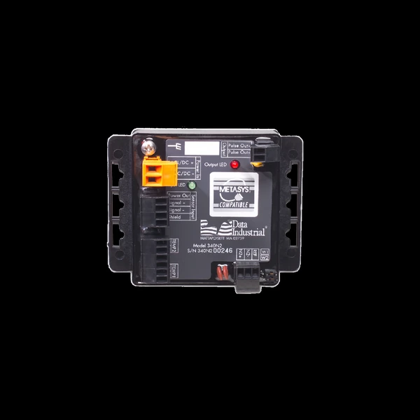
The 340 BTU energy transmitters turn a Data Industrial flow point into a hydronic energy meter — compact, field-programmable cast-body units that compute energy from flow and the supply-to-return temperature differential read by a matched temperature pair at the system inlet and outlet. The 340 BN/MB reports BTU over BACnet or Modbus on RS-485 and accepts matched 10 kΩ thermistors or 100 / 1000 Ω platinum RTDs; the 340N2 does the same on a Johnson Controls Metasys N2 network with a Type II thermistor pair. Accuracy on a low-ΔT loop lives in that temperature pair, so the sensors and transmitter are specified as one matched set. Both program from a PC with no pots or dip switches. For flow-only signals — analog, pulse or relay — see the 300-Series flow transmitters.
Key Features & Benefits
- Turns a flow point into a hydronic energy meter — the 340 computes energy from flow and the supply-to-return temperature differential — energy / BTU rate and total from a sensor pulse plus a matched temperature pair
- BTU on the building network — the 340 BN/MB reports over BACnet or Modbus on RS-485; the 340N2 does the same on a Johnson Controls Metasys N2 network — pick the model by the bus the building runs
- Thermistor or RTD temperature pairs — the 340 BN/MB accepts matched 10 kΩ thermistors or 100 / 1000 Ω platinum RTDs, so the sensor pair can match the line size and accuracy the loop needs
- Programmed from a PC — both models configure over a Data Industrial programming kit and Windows software with no potentiometers or dip switches to set, for precise drift-free readings
- Compact, mounts anywhere — a 3.65 × 2.95 in. cast body drops onto a panel, DIN rail or into an enclosure near the flow point
Specifications
- Function
- Thermal-energy transmitters that turn a Data Industrial flow point into a hydronic energy meter — computing energy (BTU) from flow and the supply-to-return temperature differential and reporting it on the building network
- Models
- 340 BN/MB BTU energy (BACnet / Modbus); 340N2 BTU energy (Johnson Controls Metasys N2)
340 Model Selector
| Model | Network | Temperature pair | Programming kit |
|---|---|---|---|
| 340 BN/MB | BACnet or Modbus over RS-485 | Matched 10 kΩ thermistors, or 100 Ω / 1000 Ω platinum RTDs | A301-20 |
| 340N2 | Johnson Controls Metasys N2 (RS-485) | Matched 10 kΩ (Type II) thermistors | A302-20 |
- Sensor inputs
- Any Data Industrial raw-pulse flow sensor, plus many other pulse or sine-wave devices
- Pulse output
- 340N2: pulse width adjustable to 5 s
- Temperature inputs (BTU)
- A matched temperature pair at the system inlet and outlet drives the energy calculation — the 340 BN/MB accepts a matched pair of 10 kΩ thermistors, 100 Ω or 1000 Ω platinum RTDs; the 340N2 takes a pair of 10 kΩ (Type II) thermistors
- Communication (BTU)
- 340 BN/MB: BACnet or Modbus over RS-485; 340N2: RS-485 N2 (Johnson Controls Metasys)
- Power
- 12–24V AC or 12–35V DC
- Programming
- Badger Meter Windows PC software over a Data Industrial programming kit (A301-20 for the 340 BN/MB, A302-20 for the 340N2); the K-factor and offset are taken from the sensor manual or auto-calculated from the pipe ID — no pots or dip switches to set
- Enclosure / mounting
- Compact cast body, 3.65 × 2.95 in. (93 × 75 mm), for panel, DIN-rail or enclosure mounting; the optional Weathertite field enclosure is offered on the 310 / 320 flow transmitters, not the 340 body
- Operating temperature
- Operating −20 to 158°F (−29 to 70°C) for the 340N2; 32 to 158°F (0 to 70°C) for the 340 BN/MB — a narrower low end to plan the mounting location around
- Units of measure
- Flow in gpm, gph, L/s, L/min, L/hr and ft³ or m³ per second / minute / hour; energy in BTU
Common Applications
- Hydronic energy (BTU) sub-metering on chilled- and hot-water loops
- Energy reporting into a building-automation system over BACnet or Modbus — 340 BN/MB
- Energy metering on a Johnson Controls Metasys N2 network — 340N2
- Adding energy measurement to an existing Data Industrial flow point
- Pairing with the metal-tee and insertion sensors for a complete energy point
Design & Selection Considerations
- Pick the model by the building network — the 340 BN/MB speaks BACnet or Modbus over RS-485; the 340N2 speaks Johnson Controls Metasys N2 — the bus the building automation system runs decides the model before any other spec does. Use the input form to tell us the BMS and the model names itself.
- Energy accuracy lives in the matched temperature pair — the BTU calculation is flow times the supply-to-return temperature differential, so the matched pair at the system inlet and outlet matters more than the flow reading on a low-ΔT loop — place both sensors where they see true loop temperature. Use the input form to give us the design supply / return temperatures and we’ll spec the pair with the transmitter.
- Match the sensor pair to the model — the 340 BN/MB takes matched 10 kΩ thermistors or 100 / 1000 Ω platinum RTDs; the 340N2 takes 10 kΩ Type II thermistors only — confirm the temperature sensors and the model together, not separately. Order the pair and the transmitter as one matched set.
- Program the K-factor to the sensor and pipe — the transmitter reads a raw frequency, so it must carry the flow sensor’s K-factor and offset — keyed in from the sensor manual or computed from the pipe ID — before the energy numbers mean anything. The unit is field-programmable from a PC, and PTP programming and commissioning are available as an optional, quoted service. Use the input form to send the sensor model and pipe size and we’ll quote the transmitter set up for your loop.
- Mind the 340 BN/MB’s narrower operating range — the 340 BN/MB operates from 32 to 158°F while the 340N2 runs from −20°F — a mechanical room that sees freezing temperatures needs the mounting location, or the model, chosen with that in mind. Use the input form to tell us where it mounts and we’ll flag the fit before it ships.
- Plan the mounting — panel, DIN rail or enclosure — the 340 body is larger than the 300-series (3.65 × 2.95 in.) and the Weathertite field enclosure is not offered on it, so plan a panel, DIN-rail or enclosure home near the flow point. Use the input form to give us the installation spot and the mounting hardware follows.
To match the right BTU energy transmitter:
Use the input form to tell us the flow sensor, the pipe size and the fluid — and, for energy, the supply and return temperatures — plus what the output has to do (a trip relay, a 4–20 mA loop, a scaled pulse, or Modbus / BACnet), and we’ll match the transmitter or computer to it.
Flow Meter Application Sheet ›Talk to an engineer directly — Scott Prater, Principal · 917-580-0878 · scott@pratertechnical.com
Specifications compiled by Prater Technical Partners from Badger Meter Data Industrial impeller flow-sensor product literature.