Product Overview
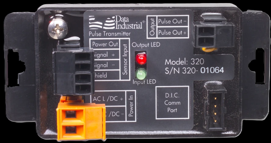
The 300-Series is the flow signal-processing family for Data Industrial sensors — compact, field-programmable cast-body units that turn a raw sensor pulse into whatever the receiver needs. The 310 outputs a loop-powered 4–20 mA analog at ±0.04% of reading; the 320 outputs a scaled pulse of programmable width and units; the 330 is a relay flow switch with programmable set / release deadband, time delays, latch and high- / low-flow alarms. All three program from a PC with no pots or dip switches and mount on a panel, DIN rail or in an optional NEMA 4X Weathertite enclosure. For hydronic energy from the same sensor pulse, the 340 BTU energy transmitters add a matched temperature pair and put BTU on the building network.
Key Features & Benefits
- One pulse, the output your receiver needs — turn a raw Data Industrial sensor pulse into a 4–20 mA loop (310), a scaled pulse (320) or a relay / flow switch (330) — one compact family covers the three signal paths
- Precise analog — the 310 holds ±0.04% of reading with a selectable damping filter and field-set scaling — no potentiometers to drift
- Loop-powered 310 — the analog transmitter runs on the 4–20 mA loop itself (9–35V DC) — two wires carry both power and signal to the PLC or DCS
- Programmable flow switch — the 330 gives independent set and release points, time delays, latch and remote reset for flow / no-flow, high / low alarm and pump control
- Programmed from a PC — all three configure over a Data Industrial programming kit and Windows software with no potentiometers or dip switches to set, for precise drift-free outputs
- Compact, mounts anywhere — a 1.75 × 2.75 in. cast body drops onto a panel or DIN rail, or into the optional NEMA 4X Weathertite enclosure (310 / 320) for field mounting
Specifications
- Function
- Signal-processing transmitters that convert a Data Industrial flow-sensor pulse into an analog loop, a scaled pulse, or a relay / flow switch output
- Models
- 310 programmable 4–20 mA analog; 320 programmable scaled pulse; 330 programmable relay (flow switch)
300-Series Model Selector
| Model | Output | Key spec |
|---|---|---|
| 310 Analog | Loop-powered 4–20 mA | ±0.04% of reading; 0–10 selectable damping; 9–35V DC loop |
| 320 Pulse | Isolated solid-state scaled pulse | Programmable units; width adjustable 50 ms–1.0 s |
| 330 Relay | Form A + Form B relays, 5A | Set / release deadband, time delays, latch & remote reset; hi / lo alarm |
- Sensor inputs
- Any Data Industrial raw-pulse flow sensor, plus many other pulse or sine-wave devices
- Input frequency
- 0.4 to 10 kHz (310 / 320); 0 to 10 kHz (330)
- Analog output
- 310: programmable, loop-powered 4–20 mA at ±0.04% of reading, 0.1% of full-scale linearity, with a selectable 0–10 damping filter
- Pulse output
- 320: isolated solid-state scaled pulse, programmable units, width adjustable 50 ms to 1.0 s
- Relay output
- 330: one Form A and one Form B relay, 5A at 30V DC / 125 / 250V AC; programmable set and release points (deadband), time delays, latch and remote reset; high- or low-flow alarm
- Accuracy
- 310 analog ±0.04% of reading, 0.1% of full-scale linearity
- Power
- 310 loop-powered 9–35V DC; 320 / 330 12–28V AC or 12–40V DC
- Programming
- Badger Meter Windows PC software over a Data Industrial programming kit (A301-20 for the 310 / 320, A301 for the 330); the K-factor and offset are taken from the sensor manual or auto-calculated from the pipe ID — no pots or dip switches to set
- Enclosure / mounting
- Compact cast body, 1.75 × 2.75 in. (44 × 70 mm), for panel, DIN-rail or enclosure mounting; an optional NEMA 4X metal or plastic Weathertite field enclosure is offered on the 310 / 320, and DIN-rail clips are available
- Operating temperature
- Operating −20 to 158°F for the 310 / 320 (−29 to 70°C) and 330 (−25 to 70°C)
- Units of measure
- Flow in gpm, gph, L/s, L/min, L/hr and ft³ or m³ per second / minute / hour
Common Applications
- 4–20 mA analog flow into a PLC, DCS or chart recorder — Model 310
- Scaled-pulse totalizing into a counter or building-automation system — Model 320
- Flow / no-flow, high- or low-flow alarm and pump control — Model 330
- Retrofitting a signal output onto an existing Data Industrial flow point
- Condensing a remote sensor’s raw frequency into a standard plant signal
Design & Selection Considerations
- Pick the transmitter by what the receiver needs — the choice follows the output: a 4–20 mA loop into a PLC or recorder is the 310; a scaled pulse into a counter or BMS is the 320; a relay flow switch or alarm is the 330. For energy on a building network, the job moves to the 340 BTU transmitters. Use the input form to tell us the signal and the receiver and we’ll name the model.
- Program the K-factor to the sensor and pipe — every transmitter reads a raw frequency, so it must carry the sensor’s K-factor and offset — either keyed in from the sensor manual or, for insert sensors, computed by the software from the pipe ID — before it reads in engineering units. The unit is field-programmable from a PC, and PTP programming and commissioning are available as an optional, quoted service. Use the input form to send the sensor model and pipe size and we’ll quote the transmitter set up for your loop.
- Confirm the sensor’s frequency sits in the input window — the 310 and 320 accept 0.4 to 10 kHz and the 330 reads 0 to 10 kHz — check the sensor’s output frequency at your minimum flow against the window before pairing. Use the input form to give us the sensor and the flow range and we’ll confirm the match.
- Set the 330’s deadband and delays to the process — the relay’s independent set and release points, time delays, and latch / remote-reset behavior are what keep a pump-control or alarm loop from chattering around the trip point — program them to the process swing, not just the nominal flow. Use the input form to tell us the trip point and what happens at it, and the settings follow.
- Power each model the way it wants — the 310 is loop-powered from 9–35V DC — the receiving loop is the supply — while the 320 and 330 take a local 12–28V AC or 12–40V DC feed. Budget the loop voltage or the local supply when you lay out the panel. The power answer is part of the model choice.
- Put the field-mounted unit in the Weathertite — the standard cast body wants a panel, DIN rail or enclosure; where the transmitter lives out at the sensor, the optional NEMA 4X metal or plastic Weathertite enclosure (310 / 320) carries it — and the −20 to 158°F operating range covers most mechanical spaces. Use the input form to tell us where it mounts and we’ll include the enclosure with the quote.
To match the right flow transmitter:
Use the input form to tell us the flow sensor, the pipe size and the fluid — and, for energy, the supply and return temperatures — plus what the output has to do (a trip relay, a 4–20 mA loop, a scaled pulse, or Modbus / BACnet), and we’ll match the transmitter or computer to it.
Flow Meter Application Sheet ›Talk to an engineer directly — Scott Prater, Principal · 917-580-0878 · scott@pratertechnical.com
Specifications compiled by Prater Technical Partners from Badger Meter Data Industrial impeller flow-sensor product literature.