Product Overview
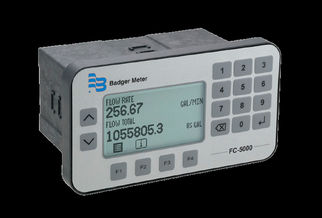
The Badger Meter FC-5000 BTU Monitor is the industrial flow / energy computer that turns a ModMAG flow meter into a complete hydronic energy meter. Pairing one flow input with two temperature inputs (supply and return), it computes energy / BTU rate and total to EN 1434 alongside flow rate and total. A 128 × 64 backlit graphical display with a full numeric keypad, Modbus / BACnet over RS-485, scaled analog and frequency outputs, Form C mechanical relays and six digital I/O make it a flexible monitoring and control station. Non-volatile memory preserves settings and totals through a power failure, and it panel-mounts or wall-mounts — the wall-mount build in a NEMA 4X / IP67 enclosure.
Key Features & Benefits
- Hydronic energy / BTU measurement — computes energy rate and total from one flow input plus two temperatures to EN 1434 — the function a flow meter cannot do on its own
- Stored or custom fluid properties — fluid characteristics are stored for the energy calculation — so a water / glycol mix reads correct BTU, not water-only numbers
- Form C mechanical relays — two 5 A relays (250V AC / 30V DC) drive pumps, valves or alarms directly; the relay build — two Form C, or one Form C plus a solid-state Form A — is chosen at order time
- Modbus & BACnet over RS-485 — EIA-485 with Modbus RTU / ASCII or BACnet selectable in firmware is standard on every BTU Monitor, with up to 255 units daisy-chained onto a BMS
- Two RTD / thermistor temperature inputs — two independent channels read Pt100 / 1000 Ω RTDs (2-, 3- or 4-wire) or Type II thermistors for the supply and return legs
- Direct-insert, thermowell or strap-on sensors — a probe range to fit the line — from in-stream R-Series styles to a clamp-on RTD for retrofit; see What to Pair It With for the matched pair
- Graphical display + keypad — a 128 × 64 backlit LCD with softkeys and a full numeric keypad
- Scaled outputs & digital I/O — two scaled analog or frequency outputs plus six digital I/O for remote reset, selected at time of ordering
- Non-volatile memory — settings and totalizer values survive a power failure
Specifications
- Function
- Microprocessor-driven industrial flow / energy computer — totalizes flow and computes hydronic energy / BTU from one flow input plus two temperature inputs
- Meter & sensor compatibility
- Pairs with the full line of Badger Meter industrial flow meters (including the ModMAG M-Series) with RTD or thermistor temperature sensors, sold as separate line items
- Measured & displayed parameters
- Flow rate, flow total, energy / BTU rate and energy / BTU total; raw and calculated sensor data plus relay, output and I/O status
- Flow-meter input
- One channel, 0.3 Hz–10 kHz; square-wave 0–30V pulse (2.5V threshold) or zero-centered sine (45 mV threshold); configurable debounce
- Temperature inputs
- Two independent channels — Pt 100 / 1000 Ω RTD (2-, 3- or 4-wire, Callendar–Van Dusen) or Type II thermistor (Steinhart–Hart)
Temperature Sensor Mounting Options
| Mount type | Description |
|---|---|
| Surface-mount (strap-on) | Clamps to the pipe exterior with heat-sink compound and heat tape — no pipe penetration and no shutdown; ideal for retrofit (Dynasonics TFX RTD). |
| Direct-insert (compression) | A Pt100 probe inserted into the flow through a compression fitting; lower cost and adjustable depth, but a brief service interruption is needed to remove it (R-Series). |
| Thermowell | A Pt100 probe in a protective well for larger pipes or pressurized systems; the probe is replaceable without draining the system (R-Series). |
- Sensor excitation output
- 12V DC sensor excitation output, ±50 mA short-circuit current
- Flow calculation
- Flow-rate uncertainty ±0.01%, with an adjustable damping function — finite- and infinite-impulse-response (FIR / IIR) digital filtering — to steady the reading
- Energy / BTU calculation
- Hydronic energy / BTU calculation meeting EN 1434
- Analog output
- Two scaled channels (option A): 0–5V, 0–10V or 4–20 mA; 16-bit resolution (0–10V and 4–20 mA), 15-bit resolution (0–5V); ±0.1% of reading, 200 ms 90-10% step response; assignable to rate, total or temperature
- Frequency output
- Two scaled channels (option F): TTL 1–4000 Hz; ±0.01%
- Relay outputs
- Two Form C mechanical relays (5 A, 250V AC / 30V DC; 5,000,000 operations), or one Form C plus one Form A solid-state relay; assignable to rate, total or temperature as a totalizing output or alarm, with optional latching. Relay configuration is selected at time of quoting / ordering
- Digital I/O
- Six independent isolated channels (0–30V input) for remote reset of relays and / or totalizers
- Communication
- Modbus RTU, Modbus ASCII or BACnet over EIA-485 (RS-485), 1200–115.2K baud; up to 255 units daisy-chained; the communications module is selected at time of quoting / ordering
- USB
- Mini-B USB (device) for field firmware updates
- Display
- 128 × 64-pixel LED-backlit graphical LCD; single or dual view (flow and/or energy rate + total)
- Keypad / interface
- Membrane overlay with domed tactile keys, softkeys and a full numeric keypad
- Power supply
- 10–40V DC or 9–28V AC RMS (50–60 Hz); 8 W maximum; isolated and over-voltage / transient / reverse-polarity protected
- Mounting
- Wall mount — includes a NEMA 4X / IP67 rated enclosure; or panel mount
- Volumetric flow units
- US / imperial gallons (and mega-gallons), liters / mega-liters, cubic meters, cubic feet, acre-feet, oil and liquid barrels, ounces or custom — per second, minute, hour or day
- Energy units
- kBTU, BTU, kW, tons of refrigeration (RT) or custom
- Temperature units
- °F, °C, Rankine or Kelvin
- Ambient temperature
- 32–130°F (0–55°C)
- Storage temperature
- −40–160°F (−40–70°C)
- Humidity
- 0–85%, non-condensing
- Operating altitude
- Up to 6,561 ft (2,000 m)
- Memory / data retention
- Non-volatile — preserves configured settings and totalizer values through a power failure; restorable to factory settings
- Weight
- Panel mount 1.25 lb (0.57 kg); wall mount 4.54 lb (2.06 kg)
- Standards & compliance
- Energy calculation to EN 1434; over-voltage Category II; pollution degree 2
Common Applications
- Hydronic heating and cooling energy / BTU monitoring
- Chilled-water and hot-water plant submetering
- Tenant and cost-allocation energy billing
- District energy and central-plant metering
- Flow totalizing and rate monitoring at an operator panel
What to Pair It With
The FC-5000 BTU Monitor computes energy — it does not measure flow or temperature on its own. A complete hydronic energy meter is the monitor plus one flow input and a matched pair of temperature sensors (supply and return), each a separate line item:
- A ModMAG flow meter — a full-bore M1000 (or M2000 / M3000 / M4000 / M5000) supplies the pulse / frequency flow input; any Badger Meter industrial flow meter with a compatible output works
- A matched pair of R-Series RTDs — 3-wire Pt100 supply- and return-side sensors — direct-insert (compression) for smaller lines, thermowell for larger or pressurized pipe — up to 500 ft from the monitor
- A non-invasive RTD alternative — surface-mount (strap-on) RTDs clamp to the pipe exterior with no penetration or shutdown, for retrofits where the line cannot be opened
To configure the FC-5000 for your system:
Use the input form to tell us your flow meter and line size — and, for energy, your supply / return temperatures — and we’ll configure the FC-5000 inputs, outputs and relays for your application.
Flow Meter Application Sheet ›Talk to an engineer directly — Scott Prater, Principal · 917-580-0878 · scott@pratertechnical.com
Specifications compiled by Prater Technical Partners from Badger Meter product datasheets.