Product Overview
The Badger Meter FC-5000 is an industrial flow computer that adds a panel-side display, control relays and added network connectivity to a ModMAG (or other Badger) flow meter. It reads the meter’s pulse / sine output, applies 100-point linearization, and shows flow rate and total — volumetric or mass — on a 128 × 64 graphical display with a full numeric keypad. Two Form C mechanical relays (5 A) drive a pump, valve or alarm directly, and the unit takes one or two flow channels so a single computer can totalize two meters. Configurable options add Modbus / BACnet over RS-485 (up to 255 units daisy-chained), scaled analog or frequency outputs and six digital I/O channels. Where the meter sits in a pit, a hazardous area or a hard-to-reach run, the FC-5000 brings relay control and a readable panel to an accessible location. Non-volatile memory preserves settings and totals through a power failure, and it panel-mounts or wall-mounts in a NEMA 4X / IP67 enclosure. For combined flow + energy measurement, see the FC-5000 Energy / BTU Monitor.
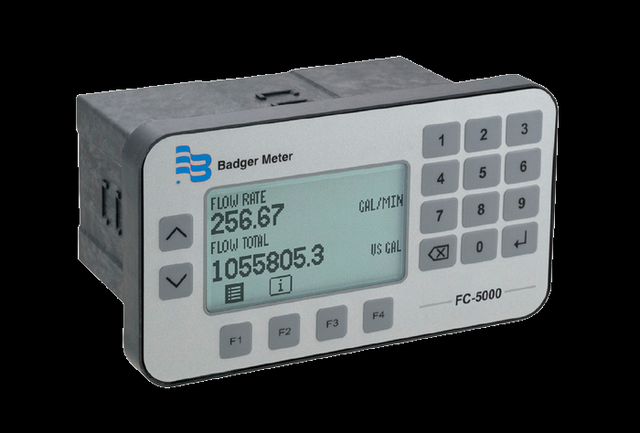
Key Features & Benefits
- Form C mechanical relays — two 5 A relays (250V AC / 30V DC) drive a pump, valve, contactor or annunciator directly — beyond a meter’s low-power outputs
- Panel operator station — a 128 × 64 backlit graphical display + full numeric keypad at the panel, with up to 255 units daisy-chained on RS-485 and queried from a control room
- Optional Modbus & BACnet networking — a selectable RS-485 module speaks Modbus RTU / ASCII or BACnet — useful when the meter lacks the protocol a BMS needs, or to query many units from one bus
- One or two flow channels — totalizes one or two meters on a single unit, each on volumetric or mass units (pounds, kilograms or custom) — the BTU configuration trades the second channel for a temperature pair
- Six digital I/O for remote reset — six isolated channels reset totalizers and / or relays remotely; configurable scaled analog or frequency outputs are available as an order option
- Custom units, scaling & linearization — maps the meter’s pulse / frequency output to any flow unit, with 100-point linearization and an adjustable FIR / IIR damping function
- Non-volatile memory — settings and totalizer values survive a power failure
Specifications
- Function
- Microprocessor-driven industrial flow computer — accepts one or two flow-meter pulse / sine inputs and totalizes, linearizes and monitors flow
- Measured & displayed parameters
- Flow rate and flow total — volumetric or mass; raw and calculated flow data plus relay, output and I/O status
- Flow-meter input
- One or two independent channels, 0.3 Hz–10 kHz; square-wave 0–30V pulse (2.5V threshold) or zero-centered sine (45 mV threshold); configurable debounce, with 100-point linearization
- Sensor excitation output
- 12V DC sensor excitation output, ±50 mA short-circuit current
- Flow calculation
- Flow-rate uncertainty ±0.01%, with an adjustable damping function — finite- and infinite-impulse-response (FIR / IIR) digital filtering — to steady the reading
- Analog output
- Two scaled channels (option A): 0–5V, 0–10V or 4–20 mA; ±0.1% of reading, 16-bit; assignable to rate or total
- Frequency output
- Two scaled channels (option F): TTL 1–4000 Hz; ±0.01%
- Relay outputs
- Two Form C mechanical relays (5 A, 250V AC / 30V DC; 5,000,000 operations), or one Form C plus one Form A solid-state relay; assignable to rate or total as a totalizing output or alarm, with optional latching. Relay configuration is selected at time of quoting / ordering
- Digital I/O
- Six independent isolated channels (0–30V input) for remote reset of relays and / or totalizers
- Communication
- Modbus RTU, Modbus ASCII or BACnet over EIA-485 (RS-485), 1200–115.2K baud; up to 255 units daisy-chained; the communications module is selected at time of quoting / ordering
- USB
- Mini-B USB (device) for field firmware updates
- Display
- 128 × 64-pixel LED-backlit graphical LCD; single or dual view (flow rate and / or flow total)
- Keypad / interface
- Membrane overlay with domed tactile keys, softkeys and a full numeric keypad
- Power supply
- 10–40V DC or 9–28V AC RMS (50–60 Hz); 8 W maximum; isolated and over-voltage / transient / reverse-polarity protected
- Mounting
- Wall mount — includes a NEMA 4X / IP67 rated enclosure; or panel mount
- Volumetric flow units
- Volumetric — US / imperial gallons (and mega-gallons), liters / mega-liters, cubic meters, cubic feet, acre-feet, oil and liquid barrels, ounces or custom; mass — pounds, kilograms or custom; per second, minute, hour or day
- Ambient temperature
- 32–130°F (0–55°C)
- Storage temperature
- −40–160°F (−40–70°C)
- Humidity
- 0–85%, non-condensing
- Operating altitude
- Up to 6,561 ft (2,000 m)
- Memory / data retention
- Non-volatile — preserves configured settings and totalizer values through a power failure; restorable to factory settings
- Weight
- Panel mount 1.25 lb (0.57 kg); wall mount 4.54 lb (2.06 kg)
- Standards & compliance
- Over-voltage Category II; pollution degree 2
Common Applications
- Relay-driven pump, valve or alarm control from flow rate or total
- A panel operator station for a meter in a pit, vault or hazardous area
- Adding optional BACnet / Modbus networking to a meter that lacks it
- Central totalizing of many meters on one RS-485 network
- Totalizing two flow meters, or reading flow as a mass rate, on one unit
What to Pair It With
The FC-5000 reads a flow meter’s pulse / sine output — it needs a meter to monitor. Pair it with a ModMAG M-Series mag meter (or any Badger meter with a pulse / frequency output):
- ModMAG M1000 or M2000 — the everyday pairing — a full-bore mag meter on conductive liquids, its pulse / frequency output totalized, linearized and relay-controlled at the panel. See M1000 and M2000
- ModMAG M3000 or M4000 — a Class I Division 2 or Division 1 mag meter in a classified area, with the FC-5000 mounted out in a safe location for the operator readout and relays. See M3000 and M4000
- RTD or thermistor temperature sensor — optional — one temperature input lets the unit temperature-compensate a viscosity-sensitive reading; a supply / return pair turns it into the FC-5000 BTU Monitor
Design & Selection Considerations
- Decide whether the meter already does the job — on a transmitter that already integrates a local readout, a 4–20 mA loop and the BMS protocol you use, a flow computer may add nothing — check the meter’s own outputs first. The FC-5000 earns its place when you need a mechanical relay to switch a pump or valve, a panel readout where the meter is out of reach, a protocol the meter lacks, two meters on one unit, or one bus aggregating many meters’ totals. Spec the computer for what the meter cannot do — not as a default add-on.
- Match the input to the meter’s output — the input is configured per meter as either a 0–30V square-wave pulse (2.5V threshold) or a zero-centered sine (45 mV threshold), 0.3 Hz–10 kHz. Confirm the meter’s output type and frequency range fall in that window before pairing, and set the debounce for a noisy contact source. A signal that sits outside the input window will not totalize reliably.
- Choose the relay form and scaled outputs at order time — the relay block ships in one of two forms — a dual mechanical pair, or one mechanical plus a solid-state relay — and the two scaled channels are ordered as analog (option A) OR frequency (option F), not both. These are set at the time of order, so list the loads you must switch and the signals you must retransmit up front. The output and relay set is fixed by the part number, so size it to the job before ordering.
- Plan the RS-485 bus for multiple units — up to 255 FC-5000 units run on one EIA-485 daisy-chain, each individually addressed and queried for rate, total and status from a control room. Plan the addressing and bus wiring for the full count up front so a later unit drops onto the same chain. Lay out the network for the final unit count, not just the first.
To configure the FC-5000 for your system:
Use the input form to tell us your flow meter and line size — and we’ll configure the FC-5000 for the inputs, outputs and relays needed for your application. For flow + energy use the FC-5000 BTU Monitor instead.
Flow Meter Application Sheet ›Talk to an engineer directly — Scott Prater, Principal · 917-580-0878 · scott@pratertechnical.com
Specifications compiled by Prater Technical Partners from Badger Meter product datasheets.