Product Overview
The ModMAG M5000 is Badger Meter’s battery-powered electromagnetic (mag) flow meter for remote and off-grid sites without power-line access. Running on internal 3.6V lithium batteries with a standard 10-year life — optionally up to 20 years on sizes 6 in. (DN 150) and smaller — it measures by Faraday’s law of induction at ±0.4% (of measured value ±2 mm/s) across 1/2–24 in. (DN 15–600) lines, with no moving parts and no pressure loss. A low-power 16-bit microcontroller with programmable sampling drives a two-line LCD, on-board data logging and an Absolute Digital Encoded output for AquaCUE connectivity. PTFE, hard-rubber or ETFE liners and Hastelloy C or 316 stainless electrodes suit potable, reclaimed and ground water that carries a moderate amount of solids, and the meter is NSF listed and OIML/MID/AWWA water-meter approved.
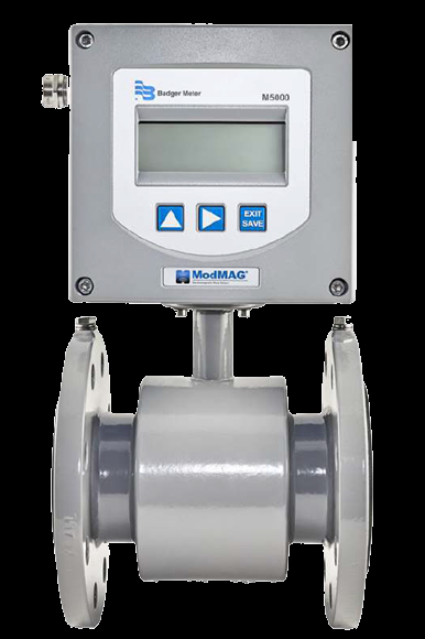
Key Features & Benefits
- Runs for years with no power wiring — self-contained lithium power means no AC or DC supply to run to the meter — a standard 10-year service life on the internal pack; the answer for remote and off-grid sites (full battery and dual-pack detail in the specifications)
- ±0.4% accuracy — of measured value ±2 mm/s — independent of fluid viscosity, density and temperature, and largely independent of flow profile
- No moving parts — an open, unobstructed flow tube means no pressure loss and virtually no maintenance
- On-board data logging — about 7,000 records at a 1 min–24 h interval, read out over Modbus or IrDA — no external hardware
- Low-power design — a 16-bit microcontroller with programmable 1–63 s sampling conserves battery life
- Automatic empty-pipe detection — a dedicated third electrode flags an empty pipe and clears itself
- Smart-metering ready — an Absolute Digital Encoded output pairs with Badger AquaCUE cellular endpoints
- Integral or remote Display-I/O — mount on the detector or remotely (bracket supplied)
- Drinking-water listed — NSF listed for potable and reclaimed water
Specifications
- Measurement principle
- Electromagnetic — Faraday’s law of induction, with a pulsed-DC field for zero-point stability. No moving parts and an open flow tube, so there is no pressure loss; accuracy is not affected by temperature, pressure, viscosity or density.
- Accuracy
- ±0.4% of measured value ±2 mm/s (independent of viscosity, density and temperature); OIML/MID: ±1% at ≥1.2 ft/s (0.35 m/s), 2–24 in. (DN 50–600), 0d up / 0d downstream
- Repeatability
- ±0.1%
- Flow velocity range
- 0.03–10 m/s (0.1–32.8 ft/s)
- Line sizes
- 1/2–24 in. (DN 15–600)
- Liner materials
- PTFE (1/2–24 in. / DN 15–600), hard rubber (1–24 in. / DN 25–600) and ETFE (12–24 in. / DN 300–600)
- Electrode materials
- Hastelloy C (standard); optional Tantalum, Platinum/Gold plated, Platinum/Rhodium, or 316 stainless steel
- Process connections
- Flange types DIN, ANSI, JIS, AWWA and more; material carbon steel (standard), stainless steel 304/316 (optional)
- Body / sensor material
- Meter housing carbon steel, painted (standard); optional stainless steel 304/316 or C5M-painted finish
- Process / fluid temperature
- Remote Display-I/O: PTFE to 302°F (150°C), hard rubber to 178°F (80°C). Meter-mounted Display-I/O: PTFE to 212°F (100°C), hard rubber to 178°F (80°C)
Flow Range by Line Size
| Size | DN | Flow range (US) | Flow range (metric) |
|---|---|---|---|
| 1/2 in. | 15 | 0.084–28.0 GPM | 0.318–106 l/min |
| 3/4 in. | 20 | 0.149–49.8 GPM | 0.57–188 l/min |
| 1 in. | 25 | 0.233–78 GPM | 0.88–295 l/min |
| 1-1/4 in. | 32 | 0.382–127 GPM | 1.45–483 l/min |
| 1-1/2 in. | 40 | 0.60–199 GPM | 2.26–754 l/min |
| 2 in. | 50 | 0.93–311 GPM | 3.53–1178 l/min |
| 2-1/2 in. | 65 | 1.58–526 GPM | 0.358–119 m³/h |
| 3 in. | 80 | 2.39–797 GPM | 0.54–181 m³/h |
| 4 in. | 100 | 3.73–1245 GPM | 0.85–283 m³/h |
| 5 in. | 125 | 5.8–1945 GPM | 1.33–442 m³/h |
| Size | DN | Flow range (US) | Flow range (metric) |
|---|---|---|---|
| 6 in. | 150 | 8.4–2801 GPM | 1.91–636 m³/h |
| 8 in. | 200 | 14.9–4979 GPM | 3.39–1131 m³/h |
| 10 in. | 250 | 23.3–7780 GPM | 5.3–1767 m³/h |
| 12 in. | 300 | 33.61–11,204 GPM | 127–42,411 l/min |
| 14 in. | 350 | 45.75–15,250 GPM | 173–57,727 l/min |
| 16 in. | 400 | 59.75–19,918 GPM | 226–75,398 l/min |
| 18 in. | 450 | 75.63–25,209 GPM | 286–95,425 l/min |
| 20 in. | 500 | 93.37–31,122 GPM | 353–117,809 l/min |
| 22 in. | 550 | 112.97–37,658 GPM | 428–142,549 l/min |
| 24 in. | 600 | 134.45–44,816 GPM | 509–169,645 l/min |
- Recommended straight run
- 3 pipe diameters upstream and 2 diameters downstream — for best accuracy (M-Series installation recommendation)
- Battery operation
- Standard 10-year life on internal 3.6V lithium batteries; optional up to 20 years (dual battery pack) for sizes 6 in. (DN 150) and smaller; optional external/AC-DC battery-backup model — designed for sites without power-line access; programmable 1–63 s sampling (15 s standard)
- Digital / pulse outputs
- Four galvanically isolated open-collector outputs (30V DC max, 20 mA each, to 100 Hz), plus high/low-flow, error, empty-pipe and flow-direction alarms
- Communication options
- RS-232 Modbus RTU, IrDA (infrared) and M-Bus; optional RS-485 Modbus RTU (and optional external AMR or GSM/GPRS module)
- Smart-metering connectivity
- Absolute Digital Encoded (ADE) output for pairing with AquaCUE cellular endpoints
- Remote signal cable
- Up to 100 ft (30 m) between detector and remote amplifier (remote-mount option)
- Enclosure / protection class
- NEMA 4X / IP67 standard; optional submersible NEMA 6P / IP68 (remote amplifier required)
- Nominal pressure
- Up to 1450 psi (100 bar) PED
- Display
- Two-line × 15-character LCD
- Display-I/O housing
- Cast aluminum, powder-coated
- Minimum conductivity
- ≥20 µS/cm
- Units of measure
- Gallons, ounces, MGD, liters, cubic meters, cubic feet, imperial gallon, barrel, hectoliter and acre-feet, field programmable
- Flow direction
- Unidirectional or bidirectional with two separate programmable totalizers, field programmable
- Empty-pipe detection
- Dedicated third electrode, field-tunable; flags an empty pipe and clears automatically when flow returns
- Grounding
- Stainless-steel grounding rings, or an optional built-in grounding electrode
- Ambient temperature
- −4…140°F (−20…60°C)
- Approvals & listings
- NSF/ANSI/CAN 61 and 372 (hard-rubber liner 4 in. / DN 100 and up; PTFE liner all sizes); plus OIML R49-1, MID MI-001, AWWA C715, WRAS, ACS, KTW, MCERT
Common Applications
- Remote and off-grid metering points with no power at the meter
- Water distribution networks
- Potable and reclaimed water
- Ground water and continuous-flow monitoring
- Irrigation
Design & Selection Considerations
- Keep the flow tube full — a partially full bore reads high and erratic. The standard empty-pipe-detection electrode flags a drained line and stops measuring to protect accuracy, but it will not correct a chronically low one — mount the meter in a low point or a rising run so the bore stays flooded. Air in the tube means bad numbers; pipe it so the meter never sees a half-full bore.
- Give it straight run — or specify the zero-straight-run version — turbulence off elbows, pumps, and valves skews the velocity profile and the reading. Allow roughly 3 pipe diameters upstream and 2 downstream for full accuracy; where the layout is tight, specify the M2000 OIML/MID zero-straight-run (0×DN) build that holds its rated accuracy with no straight run. Bolt a standard meter straight onto an elbow and you forfeit the rated accuracy — design the run in, or order the meter that does not need it.
- Match the liner to the fluid and its temperature — the liner is the wetted barrier, so it sets the chemical and temperature limits: PTFE / PFA / ETFE for chemicals, high temperature (to about 150°C), and potable water; hard rubber for water and abrasive / slurry service (to about 80°C). The liner — not the steel tube — sees the fluid, so spec it to the chemistry and the temperature.
- Match the electrode alloy to the fluid — Hastelloy C-22 is standard and covers most services; 316 stainless, tantalum, platinum / rhodium, or gold-/platinum-plated electrodes handle aggressive or special-purity media. The wrong electrode alloy corrodes or fouls and the signal drifts off.
- Ground the meter to the fluid — a mag meter measures millivolts and must share an electrical reference with the liquid — use grounding rings (304 / 316 stainless or Alloy C) or order the built-in grounding electrode, especially in lined or plastic pipe that insulates the fluid (rings are required on hard-rubber liners 4 in. and larger, and on all PTFE-lined sizes). Skip the grounding and you get noise, drift, and unstable readings.
- Size to velocity, not to the pipe — the meters read from 0.03 up to 10–12 m/s, but accuracy is best well above the low-velocity floor (the M5000, for one, holds ±0.5% only above 0.5 m/s). On an oversized line, drop a meter size with reducers so the velocity lands in the accurate band instead of crawling at the bottom of the span. Size the meter to the flow, then fit it to the pipe — not the other way around.
- Plan for abrasion and electrode coating in dirty service — in slurry, sludge, and scaling service a hard-rubber liner resists abrasion better than PTFE, while greasy, fatty, or scaling fluids can slowly coat the electrodes and pull the reading off over months. Spec the liner for the solids and plan periodic electrode checks. A clean install in dirty service can still drift later — design for inspection.
- Confirm the fluid conducts — and reach for the right technology if it doesn’t — an electromagnetic meter reads only a conductive liquid: the M-Series needs conductivity above 5 µS/cm (above 20 µS/cm for demineralized water), so hydrocarbons, oils, gases, and pure / DI water fall outside its range. That is a technology fit, not a dead end — for those fluids reach for ultrasonic on clean, high-purity, or DI water, vortex on steam and gas, or a turbine or positive-displacement (oval-gear) meter on oils and hydrocarbons. Check conductivity early so you size to the right meter technology from the start.
To size & select the right ModMAG M5000:
Use the input form to send your fluid, line size, conductivity and process conditions and we’ll spec the liner, electrode and Display-I/O for your application.
Flow Meter Application Sheet ›Talk to an engineer directly — Scott Prater, Principal · 917-580-0878 · scott@pratertechnical.com
Specifications compiled by Prater Technical Partners from Badger Meter product datasheets.