Product Overview
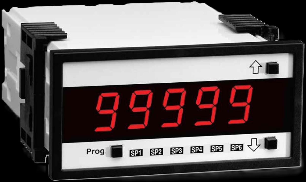
The tecsis PMD-50E (now WIKA Sensor Technology) is the panel display that completes a WIKA-ST measuring chain: it powers the strain-gauge bridge (5 / 10 / 24 V excitation), reads 0.5–20 mV/V on its 5-digit LED, and re-transmits the scaled value as 4–20 mA or 0–5/10 V while up to six setpoint relays handle alarms and optional RS-232/485, Ethernet, DeviceNet, or ModBus feed the control system. Tare, linearization, math, data logging, peak capture to 10 ms, and shunt calibration are in the box; universal 85–265 VAC power and an optional NEMA-4 front round it out. One 1/8-DIN cutout turns any mV/V sensor on this site into a working measurement point.
Key Features & Benefits
- One cutout replaces three boxes — bridge excitation, scaling to engineering units, analog retransmission, six alarm relays, and serial comms live behind a single 1/8-DIN bezel — the load-cell display, the signal conditioner, and the alarm unit collapse into one panel device. The panel shop wires one thing.
- Reads the raw bridge directly — with 0.5–20 mV/V input and selectable 5 / 10 / 24 V excitation, the PMD-50E takes the mV/V families on this site — load cells, pins, transducers — without an amplifier in between; up to four sensors are configurable. Sensor to display in one hop.
- Shunt-cal proves the loop without a load — switching a known shunt across the bridge — remote or internal — produces a predictable output step that verifies sensor, cable, and meter together, a routine check that needs no test weights and no downtime. Calibration confidence from the front panel.
- Fast enough to catch the peak — peak/valley capture at 330 ms typical — optionally down to 10 ms — holds the maximum of a press stroke or proof test that the eye (and a slow display) would miss. The reading you needed is the one it kept.
- Grows into the control system — optional RS-232/485, Ethernet, DeviceNet, and ModBus plus PID control mean the panel meter installed as a display can later feed the historian or close a loop without changing hardware. A display today, an I/O node when you need it.
Specifications
- Function
- The panel meter for the WIKA-ST sensor families: a programmable 5-digit display that excites a strain-gauge bridge, scales it to engineering units, and hands the result on as analog, relay, and serial signals — display, conditioner, and alarm unit in one 1/8-DIN cutout.
- Input & excitation
- Full-bridge pressure/load sensors, 4-wire (or 6-wire with internal shunt), 0.5–20 mV/V; excitation jumper-selectable 5, 10, or 24 VDC; up to 4 sensors configurable. Optional input classes: DC/AC voltage, current, RTD, thermocouple, LVDT, potentiometric, magnetostrictive, frequency, pH.
- Output signal
- Analog retransmission 0–5 / 0–10 VDC or 4–20 mA (or both), 16-bit — 250 µV / 0.4 µA resolution; response typ. 143 ms.
- Display
- 5-digit 0.56″ 7-segment LED (red standard; green / super-bright options), ~5 updates/s, front-panel decimal to 5 positions, over/under-range indication.
- Setpoints, relays & I/O
- Up to 6 programmable limit setpoints (option) with optically isolated I/O; PID loop control available.
- Communications
- Optional RS-232, RS-485, Ethernet, DeviceNet, ModBus.
- Accuracy & drift
- Peak/valley capture typ. 330 ms (10-ms option); tare/zero, apply-full-scale scaling, linearization, math functions, and data logging built in.
- Zero, span & shunt calibration
- RS-232-programmable configuration; shunt calibration via remote shunt or optional internal shunt resistor — verify the whole measuring chain without applying load.
- Power supply
- 85–265 VAC universal; 10–72 VDC option.
- Mounting / form factor
- Panel mount, 1/8-DIN standard cutout; 96 × 48 × 143 mm including rear connectors; 0.79 lb.
- Housing
- 94V-0 UL polycarbonate housing; optional metal case.
- Sealing & protection class
- Optional IP65 / NEMA-4 front.
- Temperature range
- Operating 0–50°C; storage −20 to +70°C; 95% RH non-condensing.
- Approvals & options
- CE (EN 61000-3/4/6, EN 61010-1).
- Build & lead time
- Configured per input class, excitation, output/relay/comms options, and front sealing. Quote-only, no public price list.
Common Applications
- Displaying and alarming any WIKA-ST mV/V load cell, load pin, or pressure transducer
- Press, test-stand, and proof-load readouts with peak capture
- Retransmitting a scaled 4–20 mA / 0–10 V value to a PLC or recorder
- Multi-sensor test benches — up to 4 configurable sensor inputs
Design & Selection Considerations
- Match the excitation to the sensor before power-up — the excitation jumper offers 5, 10, or 24 VDC and the sensor’s datasheet says which it tolerates — a 24-V jumper into a 15-V-max bridge is a warranty conversation. Set the jumper from the sensor sheet, not from habit.
- Count the alarm contacts the application really needs — setpoint relays come as options up to six — specify the alarm philosophy (warn / trip / reset differentials) at order so the meter arrives with the contacts the interlock drawing expects. Relays are ordered, not discovered.
- Pick the comms option with the destination in mind — RS-485, Ethernet, DeviceNet, and ModBus are factory options — decide whether the value ends at the operator’s eye or in the historian before the PO, because the retrofit is a new meter. The data path is a line item.
- Six-wire sensing pays on long runs — the 6-wire input with internal shunt lets the meter see the excitation actually reaching a distant cell — use it when the cable run is long enough to drop voltage, or the scale factor quietly shifts with cable temperature. Wire count is an accuracy decision.
- Protect the front to the room’s rating — the standard bezel is a dry-panel device; the optional IP65 / NEMA-4 front is what belongs on a washdown floor or outdoor enclosure door. Order the front for where the panel lives.
- Plan the tare and scaling workflow — tare, apply-full-scale, and linearization are front-panel/RS-232 functions — decide who owns them (operator vs configuration lockout) so the displayed unit stays trustworthy. A programmable display needs an owner.
To spec the right WIKA-ST panel display:
To configure the right WIKA-ST force sensor, have these ready: the capacity (and the worst-case peak load); whether the force is tension, compression, or both; how the load is introduced (through an existing pin, a ring in the force path, or a threaded line); the output you need (4–20 mA, 0–10 V, mV/V, CANopen, or wireless) and the cable run; the environment (temperature, washdown, classified area); any certification (ATEX/IECEx, functional safety); and, for a load pin, the existing pin dimensions to match. A legacy tecsis part number is fine — send it and we cross-reference the current WIKA-ST equivalent.
Force & Pressure Application Sheet ›Talk to an engineer directly — Scott Prater, Principal · 917-580-0878 · scott@pratertechnical.com
Specifications compiled by Prater Technical Partners from WIKA product datasheets.