Product Overview
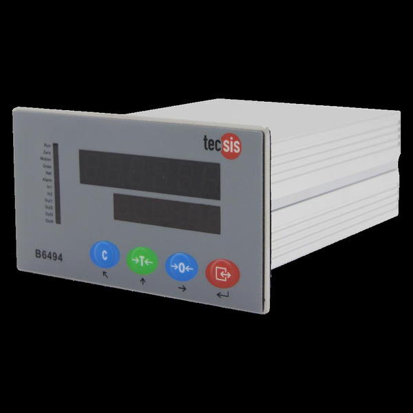
WIKA-ST digital indicators put the measuring chain’s number in the panel and its alarms on contacts. The DI25 is the universal process indicator: thermocouples, RTDs, DC current, and DC voltage on one keypad-selectable input, a dual red/green LED, three alarm relays, 4–20 mA retransmission, and an optional 24-V transmitter supply — front-sealed to IP66. The B6494 is the weighing indicator: it excites up to six 350-Ω load cells directly, converts at up to 960 Hz, and brings scale logic — tare, gross/net, motion detection, targets — plus MODBUS-RTU over RS-232/485 and four switching outputs. Between them, every WIKA-ST signal — conditioned or raw bridge — gets a panel readout.
Key Features & Benefits
- Two indicators, one decision rule — if the signal is already conditioned — a transmitter’s 4–20 mA, a thermocouple, an RTD — the DI25 displays and alarms it; if the signal is a raw load-cell bridge, the B6494 excites it, converts it, and weighs with it. The selector table below is the whole choice. Match the indicator to the signal, not the brochure.
- The DI25 powers the transmitter it reads — the P24 option supplies DC 24 V / 30 mA from the indicator — a 2-wire pressure transmitter loops through the display with no separate power supply, two devices and done. A one-loop measuring point from one panel cutout.
- Weighing logic, not just a number (B6494) — tare, gross/net, auto-zero tracking, motion detection, peak mode, and target setpoints are scale functions living in the indicator — batching against a target works out of the box instead of being ladder logic. The indicator already knows it is a scale.
- MODBUS-RTU with remote calibration (B6494) — dual serial ports (RS-232 + RS-485 to 600 m) expose the full register map — weights, status, even calibration — so the PLC or SCADA reads the scale digitally and a technician can recalibrate over the bus. The weighbridge joins the network, not just the wiring duct.
- Galvanic separation where loops meet power (DI25) — input, output, and supply are electrically separated and dielectric-tested at 1.5 kV — the ground loop that plagues panel retrofits is designed out. The display does not become the plant’s accidental ground path.
Specifications
- Function
- Panel-mount digital indicators — the operator-facing number plus the alarm contacts of a measuring chain. Two complementary units: the DI25 reads conditioned process signals (4–20 mA, DC voltage, thermocouple, RTD), while the B6494 reads the raw load-cell bridge directly and adds weighing logic.
- Input & excitation
- DI25: keypad-selectable multi-function input — 10 thermocouple types, Pt100/JPt100 RTD, 2 DC-current ranges (50-Ω shunt), 4 DC-voltage ranges. B6494: one load-cell input driving up to 6 × 350-Ω cells in parallel, ~5 V excitation, 4-wire.
DI25 or B6494 — pick by the signal
| DI25 | B6494 | |
|---|---|---|
| Reads | Conditioned signals — TC (10 types), RTD, DC current, DC voltage | Raw load-cell bridge — up to 6 × 350 Ω cells, ~5 V excitation |
| Best at | Displaying + alarming any process loop | Being the scale head — tare, gross/net, targets, peak |
| Alarms / I/O | 3 relays (3 A 250 VAC) + event input | 4 switching outputs + 2 inputs |
| Retransmission | 4–20 mA (0.3% span) | 4–20 mA / 0–5 V / 0–10 V |
| Comms | Not stated | RS-232 + RS-485, MODBUS-RTU |
| Power | 100–240 VAC or 24 VAC/DC | 24 VDC |
| Extra | Optional 24-V transmitter supply (P24); IP66 front | Delta-sigma A/D to 960 Hz; remote calibration over MODBUS |
- Output signal
- DI25: 4–20 mA retransmission (12,000 counts, 0.3% of span, load ≤550 Ω); optional 24-V transmitter supply. B6494: one analog output, configurable 4–20 mA / 0–5 V / 0–10 V.
- Display
- DI25: dual 4½-digit LED — red process value over green setpoint. B6494: dual numeric LED (6-digit auxiliary) with Run / Zero / Motion / Gross / Net / Alarm status lamps and C / Tare / Zero / Menu keys.
- Setpoints, relays & I/O
- DI25: 3 relay alarm outputs standard (1a contacts, 3 A 250 VAC, hysteresis, energized/de-energized selectable, alarm hold) + event input. B6494: 4 switching outputs + 2 switch inputs, mappable to positive/negative targets, system alarm, or test.
- Communications
- B6494: independent RS-232 + RS-485 ports with MODBUS-RTU (incl. remote calibration registers), 1,200–57,600 baud, RS-485 to 600 m. DI25: no serial protocol stated.
- Accuracy & drift
- B6494: delta-sigma conversion at 120–960 Hz sample rates with digital filtering, auto-zero tracking, motion detection, and 2-/3-point or free-weight calibration. DI25 retransmission within 0.3% of span (400-ms response).
- Zero, span & shunt calibration
- DI25: input class, scaling, and alarms from the keypad. B6494: tare/zero, capacity and increment scaling, peak mode, over/under-capacity handling — calibration also writable over MODBUS.
- Power supply
- DI25: 100–240 VAC or 24 VAC/DC (≤10 VA). B6494: 24 VDC, ≤6 W.
- Mounting / form factor
- Both flush panel-mount in the standard 92 × 45-mm cutout class — DI25: 96 × 48 × 100 mm; B6494: 110 × 62 × 150 mm.
- Housing
- DI25: black polycarbonate case, ~300 g.
- Sealing & protection class
- DI25: front IP66 (rear IP00 — enclosure-side protection by the panel). B6494: not stated.
- Temperature range
- DI25: 0–50°C, 35–85% RH. B6494: −10 to +50°C operating, 10–95% RH non-condensing.
- Approvals & options
- DI25: input/output/power galvanically separated — 1.5 kV AC dielectric between circuits, 10 MΩ insulation.
- Build & lead time
- Ordered by model code (input class, power, options — e.g. DI25 P24 transmitter supply). Quote-only, no public price list.
Common Applications
- Panel display and alarming of transmitter loops — pressure, temperature, force (DI25)
- Scale-head duty on load-cell platforms, hoppers, and vessels (B6494)
- Batching to target weights with switching outputs (B6494)
- Feeding weights and status to PLC/SCADA over MODBUS-RTU (B6494)
Design & Selection Considerations
- The DI25 does not read a bare bridge — its inputs are conditioned-signal classes (TC / RTD / DC) — a mV/V load cell needs the B6494, a PMD-50E, or an amplifier ahead of a DI25. Check the signal class before the panel cutout is punched. The cheapest mistake to make on paper, the most annoying in sheet metal.
- Alarm-relay behavior is a configuration contract — energized-vs-de-energized, hysteresis, and alarm hold decide what happens on power loss and on chattering signals — set them to the interlock philosophy and record the settings with the loop docs. A relay that fails the wrong way was configured, not defective.
- Size the B6494’s cell count and increments up front — six 350-Ω cells is the drive limit, and capacity/increment scaling defines what a displayed count means — plan the platform’s cell count and the legal-for-trade question (these are process indicators, not certified trade meters) before ordering. Scale arithmetic is part of the spec.
- Protect the rear of the panel — the DI25’s IP66 is the front bezel only — the rear is IP00 and relies on the enclosure; the B6494 prints no rating at all. Both belong inside a panel rated for the room. The cutout inherits the enclosure’s duty.
- Retransmission is not a copy of the display — the DI25’s 4–20 mA output carries its own spec — 0.3% of span at 400-ms response — so a control action taken on the retransmitted value has a slower, coarser signal than the front-panel digits suggest. Alarm locally, trend remotely. Know which number the loop actually gets.
- Manual-grade sourcing — confirm the current build at quote — both units are documented here from operating manuals; ordering codes and current options are confirmed against the factory at quotation. Treat the page as selection; the quote carries the current data.
To spec the right WIKA-ST digital indicator:
To configure the right WIKA-ST force sensor, have these ready: the capacity (and the worst-case peak load); whether the force is tension, compression, or both; how the load is introduced (through an existing pin, a ring in the force path, or a threaded line); the output you need (4–20 mA, 0–10 V, mV/V, CANopen, or wireless) and the cable run; the environment (temperature, washdown, classified area); any certification (ATEX/IECEx, functional safety); and, for a load pin, the existing pin dimensions to match. A legacy tecsis part number is fine — send it and we cross-reference the current WIKA-ST equivalent.
Force & Pressure Application Sheet ›Talk to an engineer directly — Scott Prater, Principal · 917-580-0878 · scott@pratertechnical.com
Specifications compiled by Prater Technical Partners from WIKA product datasheets.