Product Overview
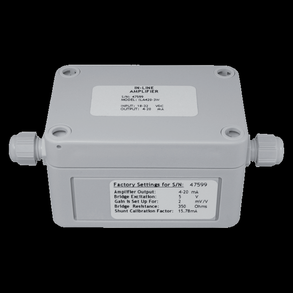
WIKA-ST (tecsis) in-line and in-cable amplifiers solve the mV/V problem at its source: a bridge sensor’s millivolt output is conditioned at the sensor and travels as ±5/±10 V or 4–20 mA. Pick the mounting form — the ILA box on the machine (IP66, ±0.02% FS, shunt-cal relays, DC–5 kHz), the ICE barrel spliced into the cable (IP67, ±0.03% FSO, incl. a loop-powered 2-wire 4–20 mA version), or an internal amplifier board ordered inside the sensor itself — then pick the output class in the table below. Together they let any mV/V load cell, pin, or transducer on this site read straight into a PLC.
Key Features & Benefits
- Amplify at the sensor, not at the panel — a raw mV/V signal degrades with every meter of cable; conditioning it at the cell — box, barrel, or board — sends a ±10 V or 4–20 mA signal down the long run instead, straight into a PLC analog card. The noisy part of the trip happens at high level.
- An amplifier hidden in the cable itself — the ICE barrel is 25.4 mm of die-cast aluminum spliced inline — nothing to find panel space for, nothing on the machine to knock off, IP67 in heavy industry. The 2-wire ICE420 even powers itself from the loop. Conditioning with no footprint at all.
- Shunt-cal relays ride along (ILA) — solid-state shunt relays on the ILA board mean the standard verify-the-chain check works on a field-mounted amplifier — trigger the shunt, watch the step, trust the loop. The health check is built into the box on the machine.
- Bipolar and wide-temperature where test rigs live — the ILA-BP runs on ±15 VDC with true bipolar output for tension/compression work and an extended −20 to +158°F rating — the variant for the environmental chamber and the outdoor rig. The odd supplies and cold corners are covered.
- DC to 5 kHz — fast enough for real force events — the ILA passes signal from DC to 5,000 Hz, so press strokes, impacts, and dynamic force profiles arrive intact rather than smoothed away by a slow conditioner. The amplifier is not the bottleneck.
Specifications
- Function
- Bridge amplifiers that move the signal conditioning out to the sensor, in three mounting forms: the ILA junction-box style screws to the machine near the cell; the ICE lives in a 25.4-mm aluminum barrel spliced into the sensor cable; and the internal amplifier boards build the conditioning into the sensor housing itself — so a millivolt bridge reaches the PLC as a robust voltage or current signal.
- Input & excitation
- mV/V full-bridge sensors: ILA5 0.5–5 mV/V, ILA10 1–20, ILA420-3W and BP 0.5–6.6, all ±25% fine span; ICE 0.5–3.0 mV/V. Bridge excitation supplied: 2.5 / 5 / 10 VDC by model (ILA5: 2.5 or 5 V).
- Output signal
- Voltage: ±5 V (ILA5, ICE5), ±10 V (ILA10, ICE10), bipolar ±5/±10 V (ILA-BP). Current: 4–20 mA 3-wire (ILA420-3W, ICE420-3W) or 4–20 mA 2-wire loop-powered (ICE420). Frequency response DC–5 kHz (ILA).
ILA / ICE / internal — which amplifier for which output & mounting
| Model | Mounting | Output | Power | Sealing |
|---|---|---|---|---|
| ILA5 | Surface box | ±5 V | 11–28 VDC | IP66 / NEMA-4 |
| ILA10 | Surface box | ±10 V | 18–32 VDC | IP66 / NEMA-4 |
| ILA420-3W | Surface box | 4–20 mA (3-wire) | 18–32 VDC | IP66 / NEMA-4 |
| ILA5/10-BP | Surface box | ±5 / ±10 V bipolar | ±15 VDC | IP66 / NEMA-4 |
| ICE5 / ICE10 | In-cable barrel | ±5 / ±10 V | 12–28 VDC | IP67 |
| ICE420-3W | In-cable barrel | 4–20 mA (3-wire) | 12–28 VDC | IP67 |
| ICE420 | In-cable barrel | 4–20 mA (2-wire, loop-powered) | 9–28 VDC | IP67 |
| Internal boards | Inside the sensor | 0–5 V / 0–10 V / ±5 V / 4–20 mA (2- & 3-wire) | per class | per sensor |
- Accuracy & drift
- ILA linearity ±0.02% FS (S/N 65 dB, supply rejection >110 dB); ICE ±0.03% FSO with thermal effects to ±0.015–0.02%/10 K zero.
- Zero, span & shunt calibration
- Coarse + fine zero and span adjustments on board; ILA carries solid-state shunt-calibration relays — the system check travels with the amplifier.
- Power supply
- ILA5 11–28 VDC; ILA10 / ILA420-3W 18–32 VDC; ILA-BP ±15 VDC; ICE 12–28 VDC (ICE420 2-wire: 9–28 VDC).
- Mounting / form factor
- ILA: surface-mount box, ~3.75 × 2.5 × 2.1″, #6/#8 screws. ICE: in-cable barrel, Ø25.4 mm, ~3-ft pigtail to the sensor and ~6.5-ft output lead. Internal boards: inside the sensor (e.g. a pancake cell ordered with 0–5 V out).
- Housing
- ILA: plastic enclosure; ICE: robust die-cast aluminum barrel.
- Sealing & protection class
- ILA: IP66 / NEMA-4; ICE: IP67.
- Temperature range
- ILA standard models 5–122°F (−15 to +50°C); the ILA-BP extends to −20…+158°F (−29 to +70°C). Internal boards: to 185°F depending on output class.
- Approvals & options
- CE; reverse-voltage and short-circuit protection on the internal board classes.
- Build & lead time
- Ordered by output class and excitation; internal amplification is specified as an option ON the sensor at sensor order. Quote-only, no public price list.
Common Applications
- Reading any WIKA-ST mV/V load cell, load pin, or transducer into a PLC analog input
- Long or electrically noisy cable runs — condition at the sensor, transmit at high level
- Heavy-industry retrofits where the conditioning must live on the machine (ICE, IP67)
- Test rigs needing bipolar tension/compression signals (ILA-BP)
Design & Selection Considerations
- Choose the mounting form by who services it — the ILA box is adjustable and shunt-checkable in the field; the ICE barrel is compact and sealed but lives in the cable; an internal board is invisible but goes back to the factory with the sensor. Serviceability, not electronics, usually decides.
- 2-wire, 3-wire, and voltage are different wiring plans — the loop-powered ICE420 runs on two conductors; 3-wire current and voltage outputs need supply plus signal; bipolar ILA-BP wants ±15 VDC rails. Fix the receiver and the cable count before ordering. The output class writes the cable schedule.
- Zero and span live in the amplifier now — coarse/fine pots at the amplifier scale the system — which means calibration records, seals, and who-may-adjust rules should name the amplifier, not just the sensor. Two calibrated devices, one system number.
- Match the excitation setting to the bridge — the amplifier sources 2.5 / 5 / 10 V excitation by model and jumper — check the connected cell’s rated excitation (and its self-heating on small bridges) before selecting. The amplifier powers the sensor; make sure it does so gently.
- Respect the temperature class of the electronics — standard ILA models are rated 5–122°F — a hot machine frame or cold yard needs the BP variant or the internal high-temperature board class rather than optimism. The sensor often out-rates its amplifier; check both.
- Buy the internal board WITH the sensor — internal amplification is a build option on the sensor (the sheet’s example is a pancake cell delivered with 0–5 V out) — it cannot be added in the field, so the output decision belongs on the sensor RFQ. One line on the sensor order replaces a device in the loop.
To spec the right WIKA-ST amplifier:
To configure the right WIKA-ST force sensor, have these ready: the capacity (and the worst-case peak load); whether the force is tension, compression, or both; how the load is introduced (through an existing pin, a ring in the force path, or a threaded line); the output you need (4–20 mA, 0–10 V, mV/V, CANopen, or wireless) and the cable run; the environment (temperature, washdown, classified area); any certification (ATEX/IECEx, functional safety); and, for a load pin, the existing pin dimensions to match. A legacy tecsis part number is fine — send it and we cross-reference the current WIKA-ST equivalent.
Force & Pressure Application Sheet ›Talk to an engineer directly — Scott Prater, Principal · 917-580-0878 · scott@pratertechnical.com
Specifications compiled by Prater Technical Partners from WIKA product datasheets.