Product Overview
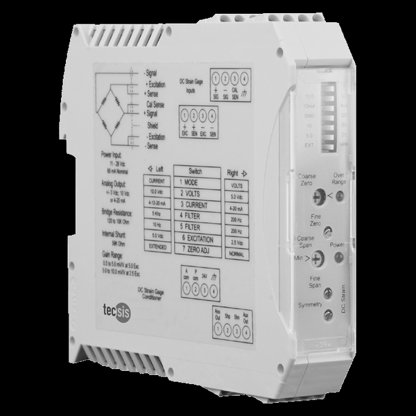
The tecsis UDA (now WIKA Sensor Technology) is the DIN-rail universal amplifier for strain-gauge measuring chains: one 22.5-mm chopper-stabilized module that excites any 120-Ω–10-kΩ bridge (2.5 / 5 V, remotely sensed, 70 mA), accepts 0.5–10 mV/V, and outputs ±5 V, ±10 V, or 4–20 mA — all selected by front-panel switches, with a 10 Hz / 200 Hz / 5 kHz filter, switch-based shunt calibration, and a symmetry trim for tension/compression duty. Linearity is better than ±0.03% FS and drift is ppm-class, so the calibration you apply is the accuracy you keep. The cabinet-side counterpart to the field-mounted ILA/ICE conditioners.
Key Features & Benefits
- One module for every bridge in the plant — 120 Ω to 10 kΩ bridges, 0.5–10 mV/V, all output classes, all set by front-panel switches — the same 22.5-mm module conditions the load cell on line 1 and the pressure transducer on line 4, and one shelf spare backs them all. Universal is a maintenance strategy.
- Chopper-stabilized: the drift spec is the feature — ±30 ppm/°C and ±10 ppm/month of offset/gain drift means the channel you calibrate in January still reads in June — the sheet’s own framing is that accuracy is limited by your calibration, not the amplifier. The electronics stopped being the error budget.
- A filter you choose, not endure — the 3-pole Butterworth filter switches between 10 Hz, 200 Hz, and 5 kHz — smooth a weighing channel, pass a press stroke — and the chopper front end averages honestly through dynamic noise either way. Bandwidth is a setting, not a compromise.
- Symmetry adjustment for tension/compression rigs — bipolar duty exposes a subtle error — negative span rarely mirrors positive span exactly — and the UDA carries a dedicated symmetry trim for it, alongside switch-based shunt calibration for chain checks. The bidirectional details are handled in hardware.
- Remote sensing keeps far cells honest — excitation is remotely sensed at up to 70 mA, so a long homerun or several paralleled cells still see the excitation the calibration assumed. The cabinet can be far from the scale and still tell the truth.
Specifications
- Function
- The cabinet-side universal signal conditioner: a 22.5-mm DIN-rail module with a chopper-stabilized low-drift amplifier that excites any conventional 4-arm strain-gauge bridge and delivers a scaled voltage or current signal — reading a true average through dynamic noise rather than chasing it.
- Input & excitation
- Full bridges from 120 Ω to 10 kΩ, adjustable 0.5–10.0 mV/V FS; remotely sensed excitation, selectable 2.5 or 5.0 V at up to 70 mA (multiple cells in parallel).
- Output signal
- Selectable ±0–5 VDC, ±0–10 VDC, 4–12–20 mA, or 4–20 mA (20% over-range on voltage), plus an auxiliary output terminal.
- Communications
- Selectable 3-pole modified Butterworth filter, −3 dB at 10 Hz, 200 Hz, or 5 kHz — match the bandwidth to the measurement instead of inheriting noise.
- Accuracy & drift
- Linearity better than ±0.03% FS; CMRR −60 dB; input impedance >10,000 MΩ; offset and gain drift ±30 ppm/°C and ±10 ppm/month — overall accuracy limited by the calibration, not the amplifier.
- Zero, span & shunt calibration
- Front-panel DIP switches set output class, level, filter, excitation, and zero; wide zero and span ranges; switch-based shunt calibration (SHP/SHN terminals); a symmetry adjustment corrects negative-span error on tension/compression duty; over-range LED.
- Power supply
- 11–28 VDC regulated, 2 W max.
- Mounting / form factor
- DIN-rail module, 114.5 × 99 × 22.5 mm wide — a channel per finger-width of rail.
- Temperature range
- −10 to +70°C (14–158°F), 5–95% RH non-condensing.
- Approvals & options
- RoHS; ISO 9001-registered manufacture.
- Build & lead time
- One universal model configured by switches — stocking one spare covers every bridge channel in the cabinet. Quote-only, no public price list.
Common Applications
- Conditioning WIKA-ST load cells, load pins, and transducers in the control cabinet
- Multi-channel test stands — one module type across all bridge channels
- Weighing channels with paralleled cells on remotely sensed excitation
- Tension/compression rigs needing bipolar output with symmetry correction
Design & Selection Considerations
- Field or cabinet — decide where conditioning lives — the UDA shines where channels concentrate in a control cabinet with short sensor runs or 6-wire sensing; a lone sensor far from the panel usually wants an ILA/ICE at the sensor instead. The cable run picks the architecture.
- Document the switch settings as configuration — output class, level, filter, excitation, and zero all live in DIP switches — capture them per channel in the loop documentation, or the next technician’s “quick check” becomes a recalibration. Switches are configuration; treat them like software.
- Budget the excitation current across paralleled cells — 70 mA covers multiple bridges in parallel, but count them: four 350-Ω cells at 5 V draw ~57 mA. Past the budget, split channels or drop the excitation voltage. Excitation is a shared resource with a hard ceiling.
- Pick the filter for the measurement, verify with the shunt — a 10-Hz setting on a dynamic press channel hides the peak; 5 kHz on a hopper scale invites noise — set the Butterworth pole to the event, then use the shunt terminals to verify the scaled chain end to end. Two switches decide what your data means.
- No printed IP rating — it belongs in an enclosure — the UDA is a cabinet device; the sheet prints environmental limits but no ingress rating, so plan the enclosure accordingly for dusty or wet rooms. The module protects the signal; the cabinet protects the module.
- Mind the common-mode window — the ±3 V common-mode range (±30 V without damage) assumes a properly referenced bridge — floating or oddly grounded sensor installs should be reviewed before wiring. Grounding errors read as drift until they read as damage.
To spec the right WIKA-ST DIN-rail amplifier:
To configure the right WIKA-ST force sensor, have these ready: the capacity (and the worst-case peak load); whether the force is tension, compression, or both; how the load is introduced (through an existing pin, a ring in the force path, or a threaded line); the output you need (4–20 mA, 0–10 V, mV/V, CANopen, or wireless) and the cable run; the environment (temperature, washdown, classified area); any certification (ATEX/IECEx, functional safety); and, for a load pin, the existing pin dimensions to match. A legacy tecsis part number is fine — send it and we cross-reference the current WIKA-ST equivalent.
Force & Pressure Application Sheet ›Talk to an engineer directly — Scott Prater, Principal · 917-580-0878 · scott@pratertechnical.com
Specifications compiled by Prater Technical Partners from WIKA product datasheets.