Product Overview
WIKA-ST vessel weighing load cells are the rocker compression cells under truck scales, tank scales, silos, and floor scales: the F1861 covers 10–50 t per cell with a self-centring rocker pin and anti-rotation lever, and the F1270 high-capacity rocker column runs 7.5 to 300 t per cell at IP69K/IP68. Accuracy is multi-cell-scale grade — linearity, repeatability, and creep each held to 0.03–0.04% Fnom — and the self-realigning geometry reads honest weight while vehicles park badly and vessels breathe. Both output 2.0 mV/V and share one accessory chain: AZK01 mounts, B6578 junction box, B1940 loop amplifier, and FE-series indicators. Pick the family by the corner load; the rest of the system is common.
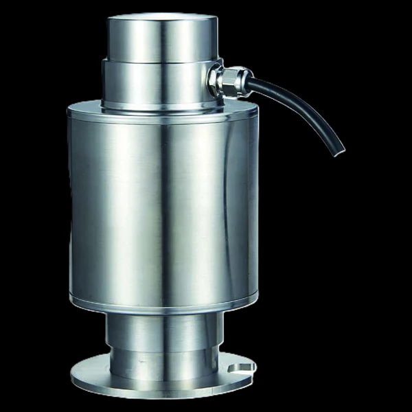
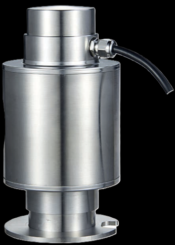
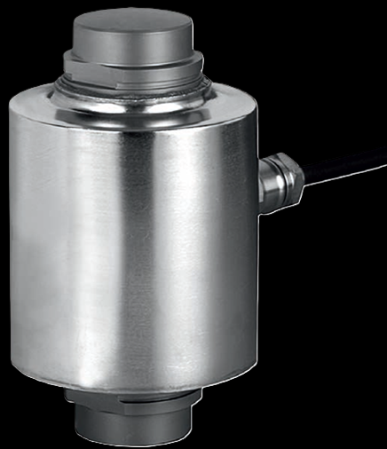
One rocker principle, two capacity ladders
Both are hermetically welded rocker compression cells at 2.0 mV/V with the same accessory ecosystem — the family picks the capacity ladder, the sealing class, and the temperature envelope.
- bilateral spherical force introduction with an anti-rotation tilting-lever pin
- tightest error terms — 0.03% F-nom linearity / repeatability / creep
- IP67; operating −20 to +60°C; 15-m cable
- force limit 150%, breaking 250% F-nom
- self-realigning rocker geometry — no precise vehicle positioning required
- IP69K, and IP68 to 2 m water depth; operating −40 to +80°C
- force limit 200%, breaking >300% F-nom, published rocking-envelope limits
- 12 / 18-m cable by size
Key Features & Benefits
- The rocker forgives the truck — a vehicle never stops in the same spot twice — the rocker geometry self-realigns within the force flow on every load change, so the F1270 explicitly does not require precise positioning of the vehicle on the platform. The cell absorbs the parking error so the weight does not.
- Hundredths-of-a-percent behavior at truck-scale capacity — 0.03–0.04% linearity, repeatability, AND creep — held simultaneously — is what lets a multi-cell scale add four or eight corners together and still produce a number worth invoicing against. Scale-grade means every error term small at once.
- Sealed like it lives outdoors, because it does — hermetically welded bodies with glass-to-metal feedthroughs; the F1270 is rated IP69K and IP68 to 2 m — a truck-scale pit that floods does not become a load-cell replacement project. Moisture is the classic slow killer of bridges; this one is welded shut.
- An anti-rotation pin where twist creeps in — the F1861’s self-resetting tilting-lever pin stops the cell rotating about its axis as the vessel works — one of the quiet failure modes of rocker installations, closed out in hardware. Degrees of freedom: exactly the ones the measurement wants, no more.
- One accessory ecosystem for the whole scale — both cells share the AZK01 mounting kit, B6578 four-cell junction box, B1940 4–20 mA cable amplifier, and the FE230 / FE430 / FE630 transmitter, indicator, and hand-held — the summing and readout chain is catalog, not custom. The system around the cells is already engineered.
Specifications
- Operating principle
- Strain-gauge compression cells built as rockers for static weighing: the load lands axially on a spherical cap, and the rocker geometry self-realigns in the force flow as the vessel or vehicle shifts — the F1861 with a self-centring rocker pin plus an anti-rotation lever pin, the F1270 as a rocker column whose radii let it install with simple force-introduction parts.
- Capacity / measuring range
- F1861: 10 / 20 / 30 / 40 / 50 t. F1270: 7.5 / 15 / 22.5 / 30 / 40 / 50 / 100 / 150 / 300 t (661,500 lb).
- Accuracy & repeatability
- F1861: linearity, repeatability, reversibility, and 30-min creep all 0.03% Fnom; TC0/TCC 0.02%/10 K. F1270: linearity, repeatability, and creep ±0.04% Fnom; TCC ≤±0.02%/10 K. Per VDI/VDE/DKD 2638 — multi-cell-scale grade.
- Output & excitation
- 2.0 mV/V full bridge (F1861 ±0.2; F1270 ±0.1); excitation DC 5–10 V (F1270 to 15 V); shielded 4-wire flying-lead PUR cable — 15 m on the F1861, 12 / 18 m by size on the F1270. Optional B1940 cable amplifier converts to 4–20 mA / 0–20 mA / 0–10 V.
- Overload & breaking force
- F1861: force limit 150% / breaking 250% Fnom. F1270: force limit 200% / breaking >300% Fnom, with a published main-rocking-direction envelope (permissible horizontal displacement and restoring force per size).
- Body material
- Hermetically welded, encapsulated measuring bodies with glass-to-metal cable feedthroughs — F1270 in stainless steel; F1861 spec table lists steel.
- Sealing & protection class
- F1270: IP69K, and IP68 to 2 m water depth; F1861: IP67 (IEC/EN 60529).
- Mounting / load introduction
- Installs under the vessel or scale structure via the AZK01 mounting kit; F1270 installs with recommended limit-stop gaps (2–5 mm by size) in the main rocking direction so the scale floats but cannot walk.
- Temperature range
- F1270: operating −40 to +80°C. F1861: rated −10 to +40°C, operating −20 to +60°C. Both: 35–85% RH non-condensing, to 2,500 m altitude.
- Approvals & options
- CE (EU declaration of conformity, RoHS); EAC. Specified per VDI/VDE/DKD 2638.
- Build & lead time
- Sized per corner load with headroom for uneven distribution; quoted with the AZK01 kits and summing/readout electronics as a system. Quote-only, no public price list.
Common Applications
- Truck scales and weighbridges
- Container and silo weighing technology
- Tank scales and floor scales
- Dosing systems and production lines weighing by vessel
- Measuring, test, and control equipment at high static loads
Design & Selection Considerations
- Static weighing is the design point — both sheets specify static force measurement — a weighbridge, silo, or tank whose load holds or changes slowly. Dynamic and cyclic force duty belongs on the fatigue-rated force families instead. Weigh with a weighing cell, cycle with a fatigue-rated one.
- Give the rocker its float — and its stops — the F1270 install calls for a defined limit-stop gap (2–5 mm by size) in the main rocking direction: the scale structure must float on the rockers, restrained by stops, not clamped rigid. A hard-piped or hard-bolted vessel bypasses the cells. Constrain the structure, not the measurement.
- Match the family to the environment, not just the load — the F1861 is rated to +40°C nominal and IP67; the F1270 runs −40 to +80°C at IP69K/IP68. An outdoor weighbridge in a freeze-thaw climate or a washdown floor scale points to the F1270 even where the F1861 capacity would do. The pit conditions pick the cell as often as the tonnage.
- Plan the summing chain with the cells — a multi-cell scale needs its corners summed and trimmed — the B6578 junction box takes up to four cells to one output, and the mV/V bridge wants a proper indicator or the B1940 amplifier for a loop signal. Order the scale, not just the cells.
- Get the load axial, centered, and free of side load — these transducers measure force introduced straight down their axis. Take an off-center or transverse load and the reading is wrong and the element can be damaged — the datasheets call for a load that is axial, centric, and free of transverse force and torque. Most field errors here are load-introduction errors, not sensor errors.
- Size so the working load lands in the upper part of the range — aim to put the routine working load high enough in the range for good resolution and signal-to-noise, with headroom for peaks. Oversize and resolution suffers; undersize and an overload event shifts the calibration. Use the input form to tell us the static load and the worst-case peak — not just the nominal.
- Know the gap between safe overload and breaking force — every unit has a safe overload it can see without losing calibration and a higher breaking force where it is destroyed. The danger zone is between them: a unit overloaded past safe but not to breaking keeps reporting plausible, wrong numbers. Any suspected overload should trigger a recalibration before you trust the data again.
- Watch cross-sensitivity where the load can swing off-axis — a side load produces a real, specified error (the F5301, for example, carries a cross-sensitivity rating for load applied at 90°). Where the loading geometry can move — a swinging sheave, a misaligned fixture — account for it in the error budget or constrain the geometry. Off-axis load is a spec line for a reason.
- Pick the output to match what is reading the sensor — a raw mV/V bridge needs a conditioning input (DAQ or indicator with a bridge card); an integrated or cable amplifier reads straight into a PLC as 4–20 mA or 0–10 V. Use 4–20 mA for long, noisy runs; 0–10 V for short test-bench runs. Decide it from the receiver and the cable distance.
- A legacy tecsis part number cross-references to a current WIKA-ST unit — the tecsis force line is now built under WIKA Sensor Technology. Use the input form to send the tecsis part number and we match the current WIKA-ST equivalent at the same spec, so a field replacement does not require re-engineering the installation. No need to re-spec from scratch on a like-for-like swap.
To spec the right WIKA-ST vessel weighing cells:
To configure the right WIKA-ST force sensor, have these ready: the capacity (and the worst-case peak load); whether the force is tension, compression, or both; how the load is introduced (through an existing pin, a ring in the force path, or a threaded line); the output you need (4–20 mA, 0–10 V, mV/V, CANopen, or wireless) and the cable run; the environment (temperature, washdown, classified area); any certification (ATEX/IECEx, functional safety); and, for a load pin, the existing pin dimensions to match. A legacy tecsis part number is fine — send it and we cross-reference the current WIKA-ST equivalent.
Force & Pressure Application Sheet ›Talk to an engineer directly — Scott Prater, Principal · 917-580-0878 · scott@pratertechnical.com
Specifications compiled by Prater Technical Partners from WIKA product datasheets.